Configuration Examples 305
# View the information about the NTP sessions of the SW4500 Ethernet
switch (you can see that a connection is established between the
SW4500 Ethernet switch and Switch3).
[SW4500] display ntp-service sessions
source reference stra reach poll now offset delay disper
**************************************************************************
[2]3.0.1.32 127.127.1.0 1 1 64 1 350.1 15.1 0.0
note: 1 source(master),2 source(peer),3 selected,4 candidate,5 configured
Configuring NTP
Broadcast Mode
Network requirements
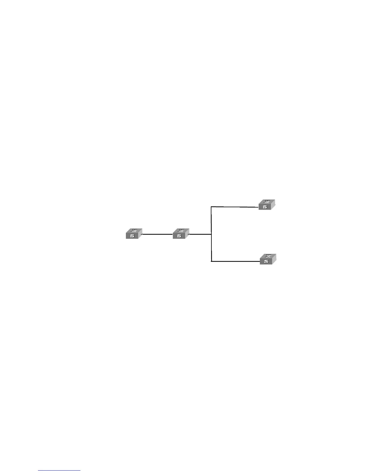
The local clock of Switch3 is set to the NTP master clock, with a stratum level of 2.
NTP packets are broadcast through Vlan-interface2. Configure SW4500-1 and
SW4500-2 to listen to broadcast packets through their own Vlan-interface2.
This example assumes that Switch3 is a switch that supports the local clock being
the master clock.
Network diagram
Figure 87 Network diagram for the NTP broadcast mode configuration
Configuration procedure
1 Configure Switch3.
# Enter system view.
<Switch3> system-view
[Switch3]
# Enter Vlan-interface2 view.
[Switch3] interface Vlan-interface 2
[Switch3-Vlan-interface2]
# Set switch3 to the broadcast server, which sends broadcast packets
through Vlan-interface2.
[Switch3-Vlan-interface2] ntp-service broadcast-server
2 Configure SW4500-1.
# Enter system view.
<SW4500-1> system-view
[SW4500-1]
# Enter Vlan-interface2 view.
[SW4500-1] interface Vlan-interface 2
[SW4500-1-Vlan-interface2]
# Set SW4500-1 to a broadcast client.
[SW4500-1-Vlan-interface2] ntp-service broadcast-client
3 Configure SW4500-2
Switch
3
SW4500 2 Switch 4
3.0.1.31/24
3.0.1.32/24
1.0.1.31/24
Vlan
-interface 2
Vlan-interface 2
-interface 2
3.0.1.32/24
1.0.1.31/24
-
-
-
SW4500-1
3.0.1.32/24
1.0.1.31/24
-
-
-
3.0.1.32/24
1.0.1.31/24
-
-
-
-1
3.0.1.32/24
1.0.1.31/24
-
-
-
3.0.1.32/24
1.0.1.31/24
-
-
-
-1
-
3.0.1.32/24
1.0.1.31/24
-
-
-
3.0.1.32/24
1.0.1.31/24
-
-
-
-1
Vlan