186 CHAPTER 10: RSTP CONFIGURATION
Table 188 Display and Debug RSTP
RSTP Configuration
Example
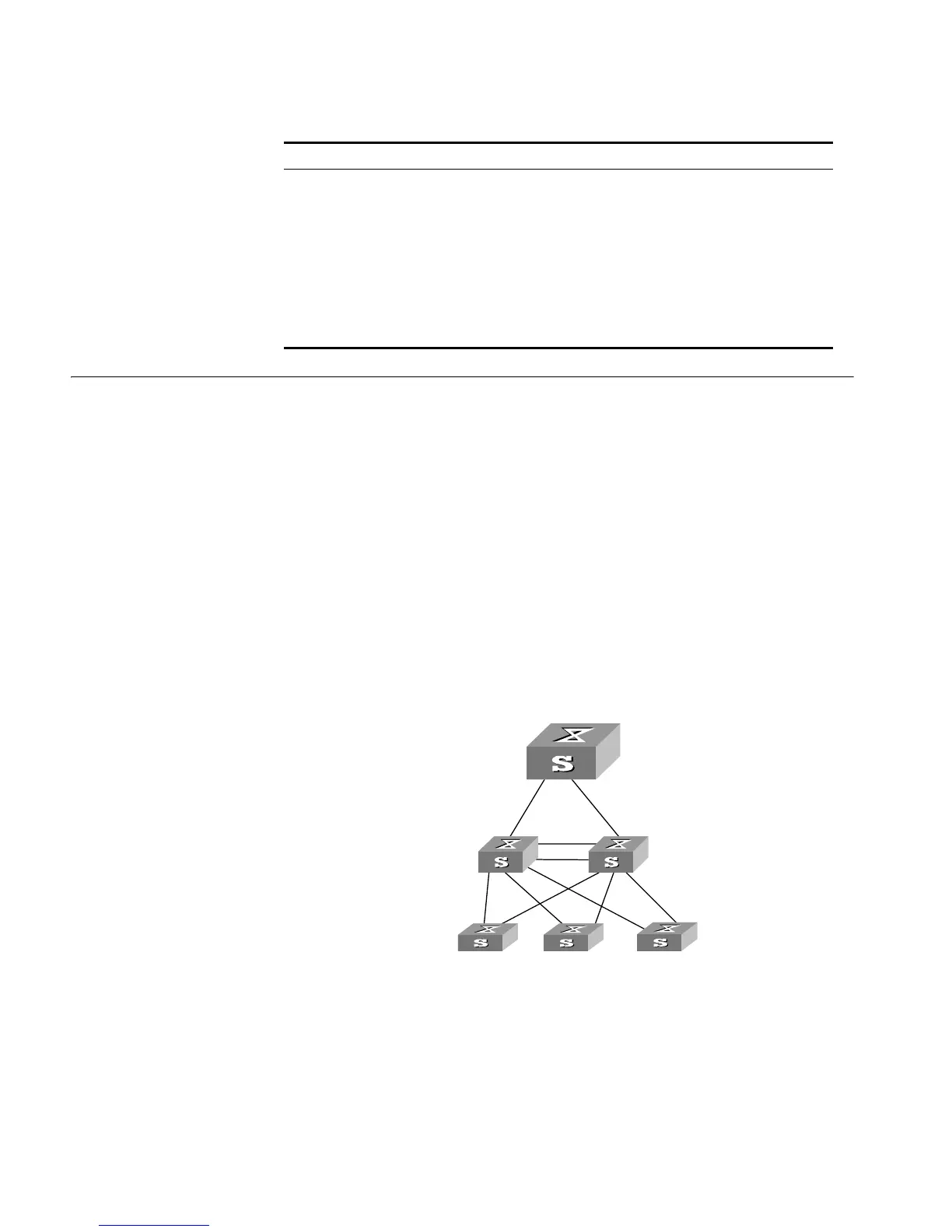
Networking Requirements
In the following scenario, Switch C serves as a standby of Switch B and forwards
data when a fault occurs on Switch B. They are connected to each other with two
links, so that, in case one of the links fails, the other one can still work normally.
Switch D through Switch F are directly connected with the downstream user
computers and they are connected to Switch C and Switch B with uplink ports.
You can configure RSTP on the Switch B through Switch F to meet these
requirements.
Only the configurations related to RSTP are listed in the following procedure.
Switch A serves as the root. Switch D through Switch F are configured in same
way basically, so only the RSTP configuration on Switch D will be introduced.
Networking Diagram
Figure 54 RSTP Configuration Example
Configuration Procedure
1 Configure Switch A
a Enable RSTP globally.
[4500]stp enable
b The port RSTP defaults are enabled after global RSTP is enabled. You can
disable RSTP on those ports that are not involved in the RSTP calculation,
Operation Command
Display RSTP configuration information about
the local Switch and the specified ports
display stp [ interface
interface_list ]
Display the list of STP-Ignored VLANs display stp ignored-vlan
Clear RSTP statistics information reset stp [ interface
interface_list ]
Enable RSTP (error/event/packet) debugging debugging stp { error | event |
packet }
Disable RSTP debugging undo debugging stp { error |
event | packet }
Switch B
Switch C
Switch A
Switch D
E1/0/1
E1/0/2
E1/0/3
E1/0/1
E1/0/2
E1/0/3
E1/1 E 1/2 E1/1
E1/2
E1/2
E1/1
E1/0/24
E1/0/23 E1/0/23
E1/0/24
Switch E Switch F
GE2/0/1 GE2/0/2