Procedure
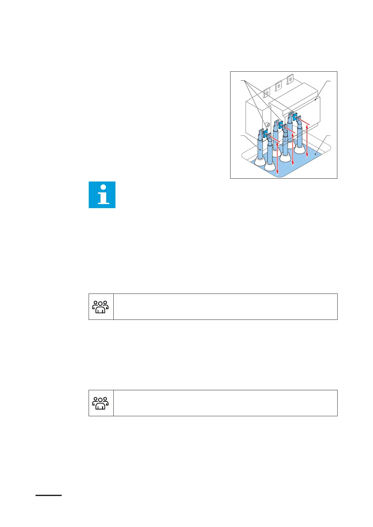
1. Cut the cables (B) to the correct
length (X) that is the distance between
the cable gland plate (C) and the
center of thet connection terminal
(A) on the main switch (D). For the
specifications, refer to section 10.15.2.
For Terra 360: (X) is 210 mm (8.27 in)
for the cables L1, L2 and L3.
Note: Make sure that the cables can move up and down a little bit, so that
you can align the cables with the connection terminals (A).
2. Attach the cable lugs to the cables. If two cables per phase are used, make sure
that you align the cable lugs with the AC terminals before you attach the cable
lug.
5.6 Mechanical installation
5.6.1 Mechanical installation procedure
Preliminary requirements
• Installation engineer
Procedure
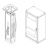
1. Install the cabinet on the base. Refer to section 5.6.2.
2. Connect the cabinet to the base. Refer to section 5.6.3.
3. Install the border covers. Refer to section 8.3.
5.6.2 Install the cabinet on the base
Preliminary requirements
• Installation engineer
Installation
9AKK108467A6398-EN | 002 65
 Loading...