5.8.2 Install the bracket of the tilt sensors
Preliminary requirements
• Installation engineer • Tilt sensor lugged
• Bracket
• Alternative bracket
• Screwdriver 3.5 mm
• Cross screwdriver size 2
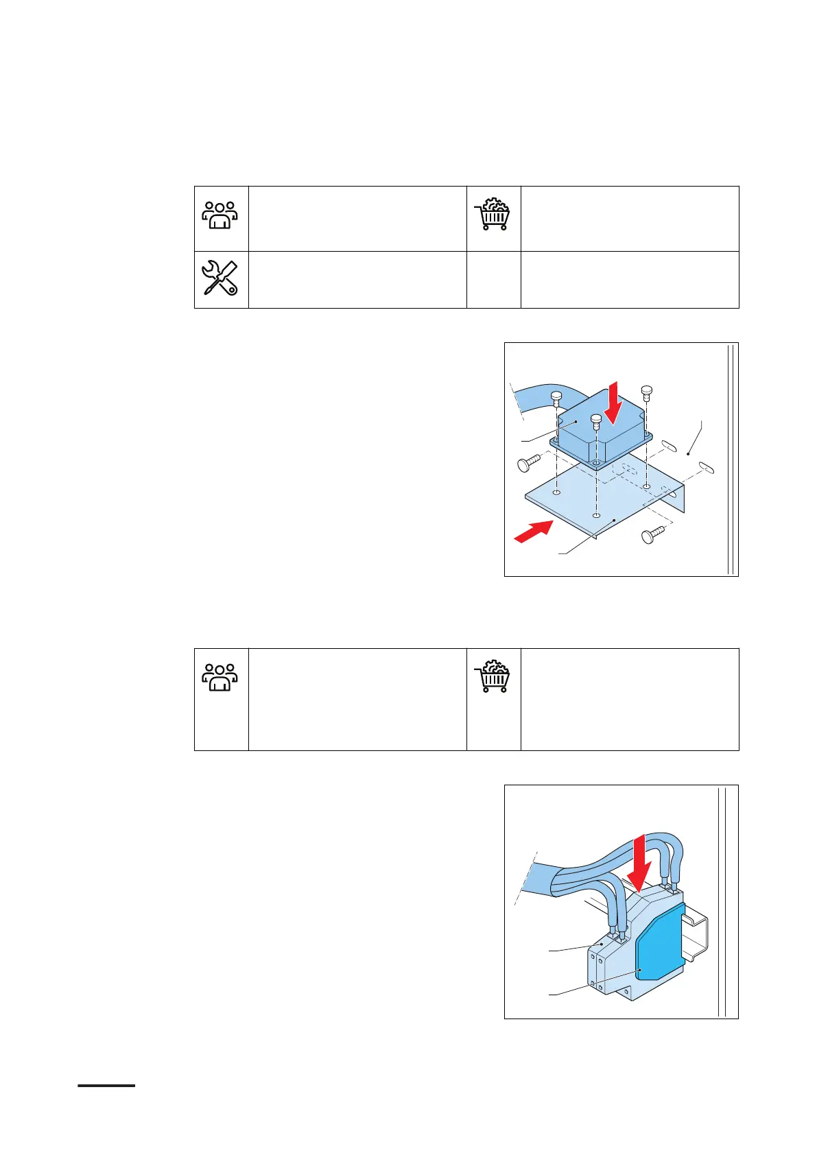
Procedure
1. Install the tilt switch (A) on the bracket
(B). Install the fasteners from the top
downwards.
2. Install the bracket in the main plate
(C). Install the fasteners.
3. If the main plate does not have fixing
holes for the tilt sensor bracket, use a
second temporary bracket and an UL
fan mounting hole.
5.8.3 Install the tilt sensors
Preliminary requirements
• Installation engineer
• Tilt sensor lugged
• Alternative bracket
• Terminal block (x2)
• Plate for terminal block
• Cable ties
Procedure
1. Connect these parts in the bottom DIN
rail:
• Terminal block (A)(x2)
• Terminal plate for the terminal
block (B)
2. Carefully guide the tilt sensor cable.
Make sure that the tilt sensor cable
does not touch the power wiring.
Apply the full cable slack.
3. Tie the tilt sensor cable to the other
cables that are on the main plate. Use
cable ties.
Installation
76 9AKK108467A6398-EN | 002

 Loading...