Rockwell Automation Publication MOTION-UM002E-EN-P - June 2016 13
Chapter 1
Create and Configure a Coordinate System
In the Studio 5000 Logix Designer® application, you use the Coordinate
System tag to configure a coordinate system. A coordinate system is a grouping
of one or more primary and ancillary axes that you create to generate
coordinated motion.
You can configure the coordinate system with one, two, or three dimensions.
The programming software supports these types of geometry:
• Cartesian
•Articulated Dependent
•Articulated Independent
• Selective Compliant Assembly Robot Arm (SCARA) Independent
• Delta three-dimensional
•Delta two-dimensional
•SCARA Delta
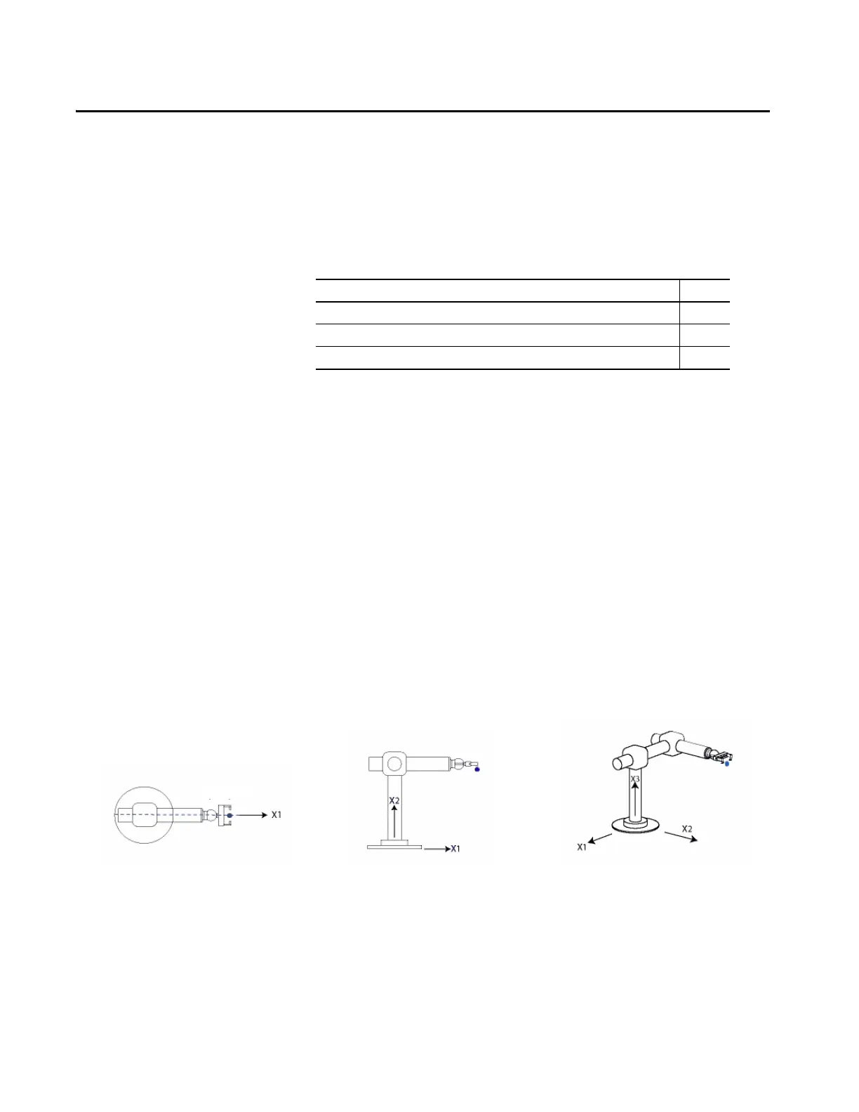
Figure 1 - Coordinate Systems with Orthogonal Axes
Topic Page
Create a Coordinate System 14
Coordinate System Wizard Dialog Boxes 17
Edit Coordinate System Properties 18
Cartesian Coordinate System Two-dimensional Cartesian Coordinate System Three-dimensional Cartesian Coordinate System

 Loading...


