22 Rockwell Automation Publication MOTION-UM002E-EN-P - June 2016
Chapter 1 Create and Configure a Coordinate System
The number of fields available for configuration in the link lengths box is
determined by the combination of the following:
• Values that are entered on the General tab for the type of coordinate
system
• Total coordinate system dimensions
• Transform dimensions
The link identifiers are L1 and L2 in the corresponding graphic. These fields
are not configurable for a Cartesian coordinate system.
Zero Angle Orientations Box
The zero-angle orientation is the rotational offset of the individual joint axes. If
applicable, enter the offset value in degrees for each joint axis. The coordinate
dimension value entered on the General tab determines the number of
available fields. The angle identifiers are Z1, Z2, and Z3 in the corresponding
graphic.
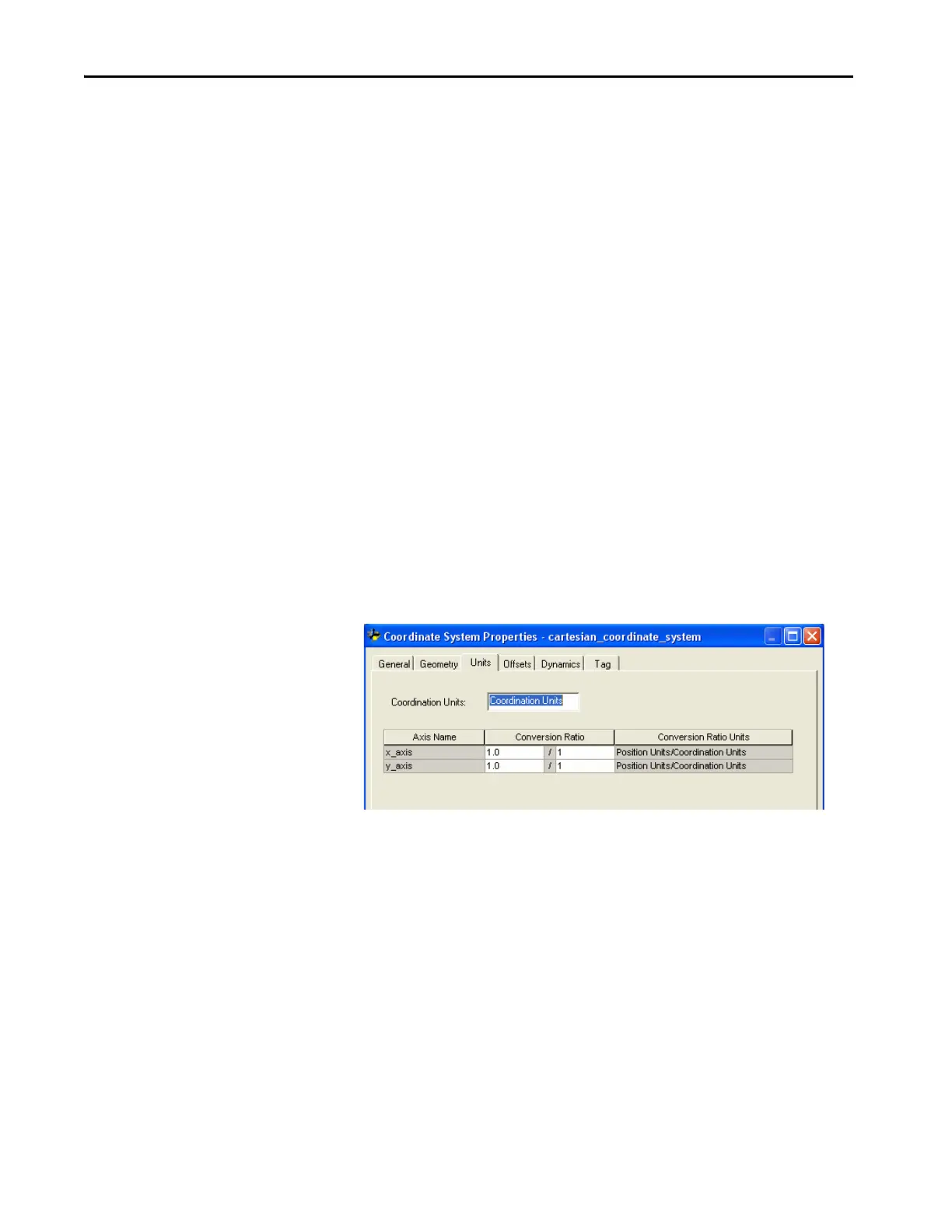
Units Tab
The Units tab of the Coordinate System Properties is where you determine the
units that define the coordinate system. This dialog box is where you define the
Coordination Units and the Conversion Ratios.
Coordination Units
The Coordination Units field lets you define the units to be used for measuring
and calculating motion-related values such as position and velocity. The
coordination units do not need to be the same for each coordinate system.
Enter units that are relevant to your application and maximize ease of use.
When you change the Coordination Units, the second portion of the
Coordination Ratio Units automatically changes to reflect the new units.
Coordination Units is the default.

 Loading...


