Rockwell Automation Publication MOTION-UM002E-EN-P - June 2016 65
Configure an Articulated Independent Robot Chapter 4
Alternate Method for Calibrating a Delta Three-dimensional Robot
Rotate each joint to a position so that the respective link is at a horizontal
position, and then perform one of the following:
• Use a MRP instruction to set all the joint angles to 0° at this position.
• Configure the values for the Zero Angle Offsets to be equal to the values
of the joints when in a horizontal position.
Configure Zero Angle Orientations for Delta Three-dimensional
Robot
For Delta robot geometries, the internal transformation equations in the Logix
Designer application are written assuming that:
• joints are at 0 when link L1 is horizontal.
• as each top link (L1) moves downward, its corresponding joint axis (J1,
J2, or J3) is rotating in the positive direction.
If you want the joint angular position when L1 is horizontal to be at any other
value than 0, then you must properly configure the Zero Angle Orientation
values on the Geometry tab of the Target Coordinate System Properties dialog
to align your joint angle positions with the internal equations.
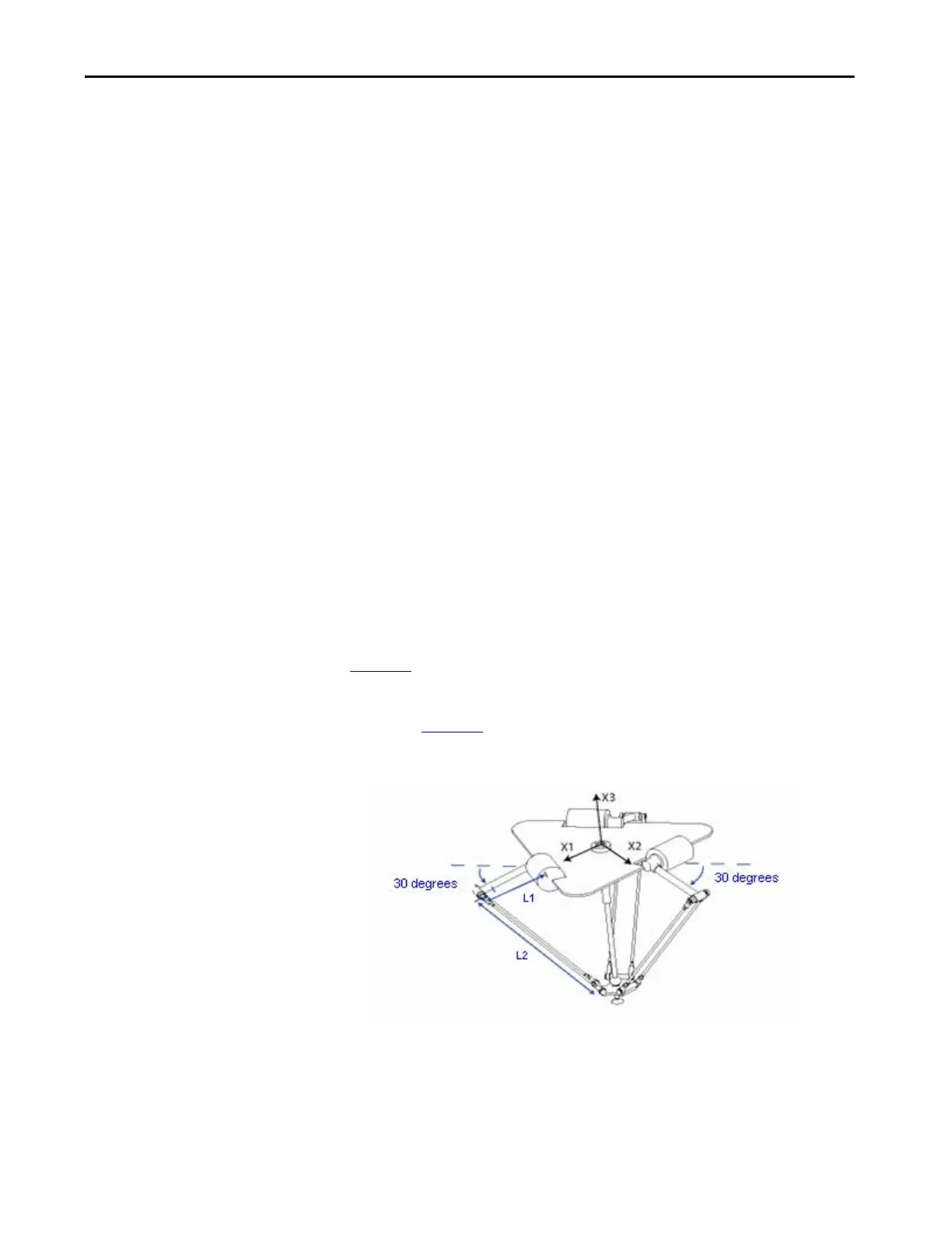
For example, if your Delta robot is mounted so that the joints attached at the
top plate are homed at 30° in the positive direction below horizontal (see
Figure 18
) and you want the Logix Designer application readout values to be
zero in this position, then you must configure the Zero Angle Orientation
values to -30° on the Geometry tab of the Target Coordinate System Properties
dialog (see Figure 19
).
Figure 18 - Delta Robot with Joints Homed at 30°

 Loading...


