62 Rockwell Automation Publication MOTION-UM002E-EN-P - June 2016
Chapter 4 Configure an Articulated Independent Robot
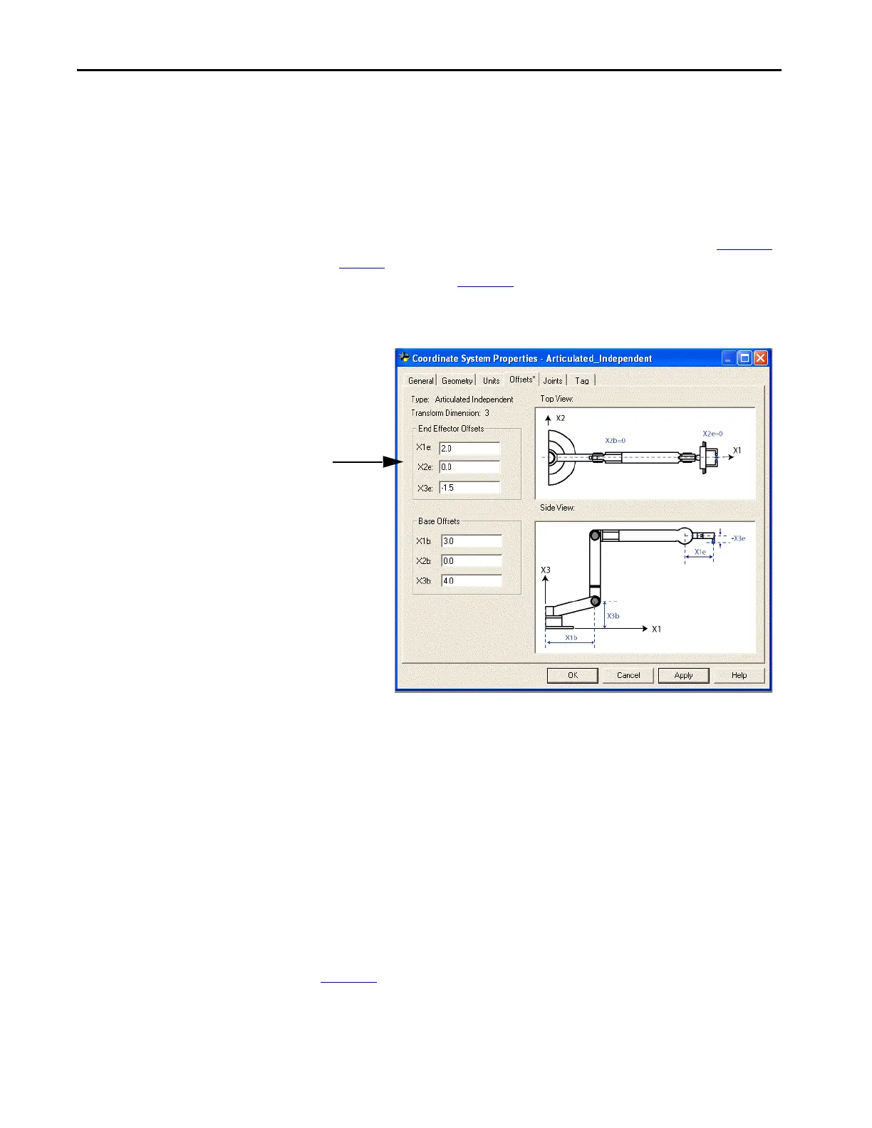
End-effector Offsets
The robot can have an end-effector attached to the end of robot link L2. If
there is an attached end-effector, then you must configure the end-effector
offset value on the Coordinate System Properties dialog. The end-effector
offsets are defined with respect to the tool reference frame at the tool tip.
Some robots also have an offset defined for the J3 joint as shown in Figure 13
on page 59
. You can account for this value when computing the X3e end-
effector offset value. In Figure 13
, the value for X3e offset is entered as the sum
of X3e1+X3e2 (-3+1.5 = -1.5). The configured value for X3e is -1.5.
Figure 16 - Example of End-effectors for an Articulated Independent Robot
Delta Robot Geometries
Logix Designer application supports three types of geometries that are often
called parallel manipulators.
•Three-dimensional Delta
•Two-dimensional Delta
•SCARA Delta
In these geometries, the number of joints is greater than the degrees of
freedom, and not all the joints are actuated (motor driven). These un-actuated
joints are typically spherical joints.
Configure a Delta Three-
dimensional Robot
Figure 17 shows a four axes Delta robot that moves in three-dimensional
Cartesian (X1, X2, X3) space. This type of robot is often called a spider or
umbrella robot.
Enter the end-effector offset values.
For the robot shown in our example, the end-effector values are:
•X1e = 2.0
•X3e = -1.5

 Loading...


