Rockwell Automation Publication MOTION-UM002E-EN-P - June 2016 53
Chapter 4
Configure an Articulated Independent Robot
Use these guidelines when configuring an Articulated Independent robot.
Reference Frame
The reference frame is the Cartesian coordinate frame that defines the origin
and the three primary axes (X1, X2, and X3). These axes are used to measure
the real Cartesian positions.
The reference frame for an Articulated Independent robot is at the base of the
robot, as shown in Figure 9
.
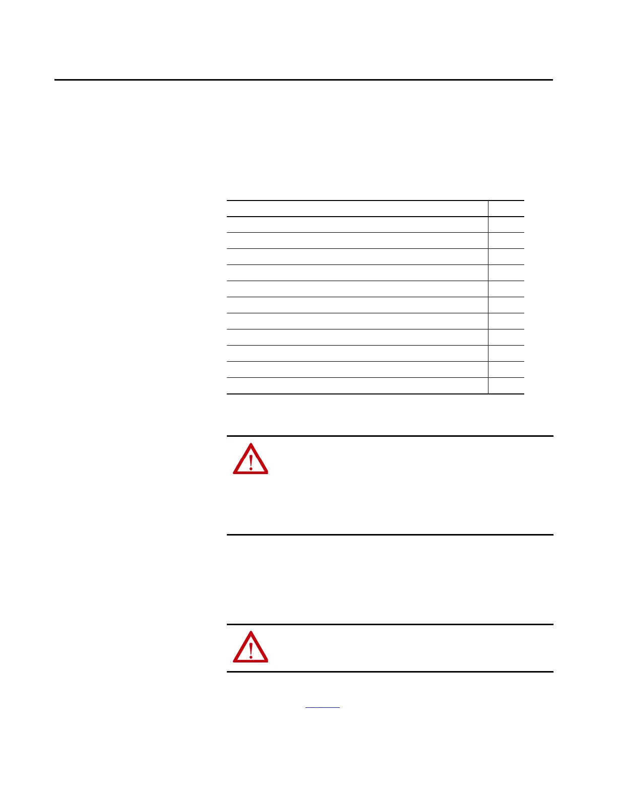
Topic Page
Reference Frame 53
Methods to Establish a Reference Frame 55
Work Envelope 57
Configuration Parameters 59
Delta Robot Geometries 62
Configure a Delta Three-dimensional Robot 62
Configure a Delta Two-dimensional Robot 71
Configure a SCARA Delta Robot 76
Arm Solutions 81
Configure a SCARA Independent Robot 84
Error Conditions 88
ATTENTION: Before turning ON the Transform and/or establishing the
reference frame, be sure to do the following for the joints of the target
coordinate system.
1. Set and enable the soft travel limits.
2. Enable the hard travel limits.
Failure to do this can allow the robot to move outside of the work envelope
causing machine damage and/or serious injury or death to personnel.
ATTENTION: Failure to properly establish the correct reference frame for
your robot can cause the robotic arm to move to unexpected positions
causing machine damage and/or injury or death to personnel.

 Loading...


