Rockwell Automation Publication MOTION-UM002E-EN-P - June 2016 97
Configure an Articulated Dependent Robot Chapter 5
Configuration Parameters
Logix Designer application can be configured for control of robots with varied
reach and payload capacities. As a result, it is important to know the
configuration parameter values for your robot including:
•Link lengths
• Base offsets
• End-effector offsets
The configuration parameter information is available from the robot
manufacturer.
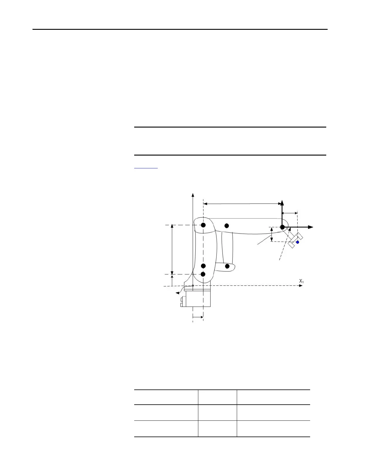
Figure 44
illustrates the typical configuration parameters for an Articulated
Dependent robot.
Figure 44 - Articulated Dependent 4
Link Lengths
Link lengths are the rigid mechanical bodies attached at joints.
IMPORTANT Verify that the values for the link lengths, base offsets, and end-effector
offsets are entered into the Configuration Parameters dialog by using the
same measurement units.
For an articulated dependent
robot with
The length of Is equal to the value of the distance
between
Two-dimensions L1
L2
J1 and J2
J2 and the end-effector
Three-dimensions L1
L2
J2 and J3
J3 and the end-effector
If the robot is two-dimensional, then X3b and X3e is X2b and X2e respectively.
L2 = 12 inches
X1e = 2 inches
L1 = 10 inches
X1b = 3.0 inches
Robot Origin
-X3e1 = 3.0 inches
Tool reference frame
X3
X3b = 4.0 inches

 Loading...


