EasyManua.ls Logo

Allen-Bradley 1756-M02AS User Manual

Allen-Bradley 1756-M02AS
132 pages
To Next Page IconTo Next Page
To Previous Page IconTo Previous Page
Page #80 background imageLoading...
Page #80 background image
80 Rockwell Automation Publication MOTION-UM002E-EN-P - June 2016
Chapter 4 Configure an Articulated Independent Robot
Configure a Delta Robot with a Negative X1b Offset
Beginning with version 17 of the application, you can use negative offsets for
the X1b base offset on both 2D and 3D delta geometries. For example, a
mechanical 2D delta robot that uses a negative X1b offset has a mechanical
configuration like the one shown here.
The base offset X1b is the value equal to the distance from the origin of the
robot coordinate system to one of the actuator joints. In the previous figure,
one of the actuator joints (P1), is on the negative side of X1. Therefore, the
base offset X1b is measured to be a value of -10 units from the origin of the
coordinate system (X1 - X2 intersection) to P1.
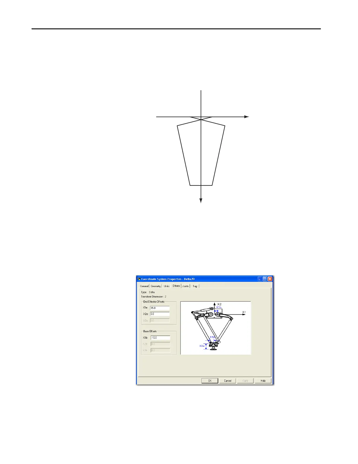
The Logix Designer application coordinate system configuration for the offset
tab used with the example in the previous figure is shown here.
This negative offset description also applies for Delta 3D and SCARA-Delta
Configurations.
+X1
+X2
X1eX1e
L2 L2
L1 L1
P1 P2
-X1b
-X1b
L1 = 50.0 units
L2 = 80.0 units
X1b = -10 units
X1e = 15 units

Table of Contents

Other manuals for Allen-Bradley 1756-M02AS

Question and Answer IconNeed help?

Do you have a question about the Allen-Bradley 1756-M02AS and is the answer not in the manual?

Allen-Bradley 1756-M02AS Specifications

General IconGeneral
BrandAllen-Bradley
Model1756-M02AS
CategoryControl Unit
LanguageEnglish

Summary

Create and Configure a Coordinate System

Coordinate System Creation Process

Steps to create a coordinate system tag, defining its type, dimension, and associated axes.

Coordinate System Configuration Options

Details on configuring coordinate system properties via tabs like General, Geometry, Units, Offsets, Joints, Dynamics, and Tag.

Configure a Cartesian Coordinate System

Configuring Motion Instructions and Blending

Programming MCLM instructions, blending moves, and understanding termination types and bit states.

Velocity Profiles and Termination Types

Explains collinear, symmetric, and triangular velocity profiles, and how to select termination types.

Configure Kinematics Coordinate Systems

Kinematics Instructions and Setup

Introduces MCTP, MCSR instructions, essential terms, robot info, and determining coordinate system type.

Preparing for Kinematics Configuration

Gathers robot information, summarizes kinematic steps, and identifies the correct coordinate system type.

Configure an Articulated Independent Robot

Reference Frame and Robot Parameters

Establishes reference frame, methods, work envelope, link lengths, base offsets, and end-effector offsets.

Robot Geometry Configuration

Detailed steps for configuring Delta (3D, 2D) and SCARA Delta robot geometries.

Arm Solutions and Kinematics

Explains arm solutions, singularities, and SCARA Independent robot setup and configuration.

Configure an Articulated Dependent Robot

Reference Frame and Robot Setup

Establishes the reference frame and methods for an Articulated Dependent robot.

Robot Configuration and Work Envelope

Covers robot parameters, work envelope, and link lengths for configuration.

Configure a Cartesian Gantry Robot

Reference Frame and Work Envelope

Setting up the reference frame and defining the work envelope for Cartesian Gantry robots.

Configuration Parameters

Notes that parameters like link lengths are not needed for Cartesian Gantry robot configuration.

Configure a Cartesian H-bot

Understanding the H-bot

Overview of H-bot mechanics, axes, and movement capabilities.

Reference Frame and Configuration

Setting up reference frame, work envelope, and parameters for Cartesian H-bots.

Configure Camming

Camming Concepts and Profiles

Defines camming, profiles (position, time), and common types like Acceleration and Run cams.

Camming Execution and Scaling

Covers scaling, execution modes (Once, Continuous), schedules (Immediate, Pending), and pending cams.

Related product manuals