76 Rockwell Automation Publication MOTION-UM002E-EN-P - June 2016
Chapter 4 Configure an Articulated Independent Robot
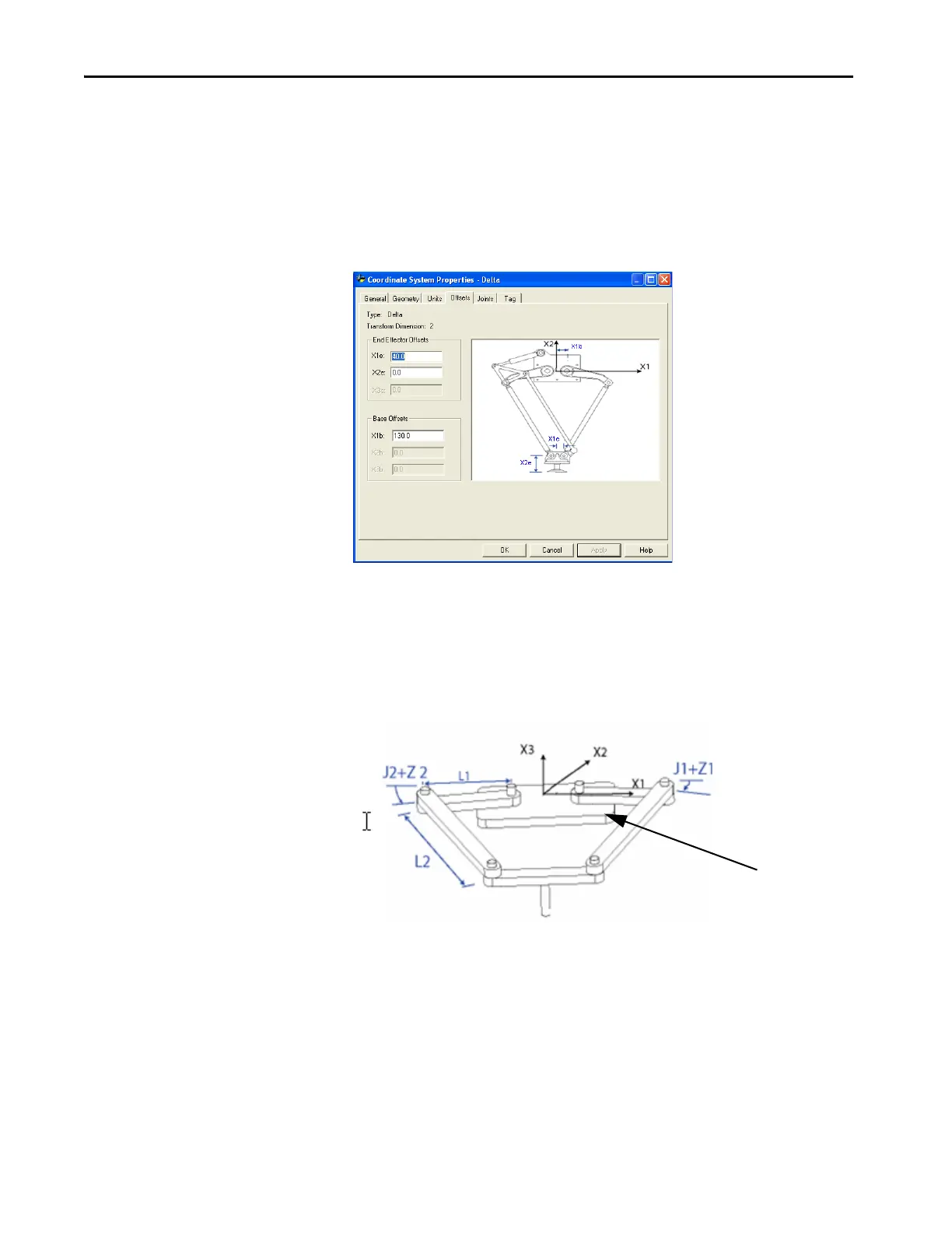
End-effector Offsets
There are two end-effector offsets available for the two-dimensional Delta
robot geometry. The value for X1e is the offset distance from the center of the
lower plate to the lower spherical joints of the parallel arms. The distance from
the lower plate to the TCP of the gripper is the value for X2e.
Figure 29 - Delta Two-dimensional Robot - Base and End-effector Offsets
Configure a SCARA Delta
Robot
The SCARA Delta robot geometry is similar to a two-dimensional Delta
robot geometry except that the X1-X2 plane is tilted horizontally with the
third linear axis in the vertical direction (X3).
Figure 30 - SCARA Delta Robot
Establish the Reference Frame for a SCARA Delta Robot
The reference frame for the SCARA Delta robot is at the center of the base
plate.
When the angles of joints J1 and J2 are both at 0, each of the two L1 links is
along the X1 axis. One L1 link is pointing in the positive X1 direction, the
other in the negative X1 direction.

 Loading...


