Rockwell Automation Publication MOTION-UM002E-EN-P - June 2016 95
Configure an Articulated Dependent Robot Chapter 5
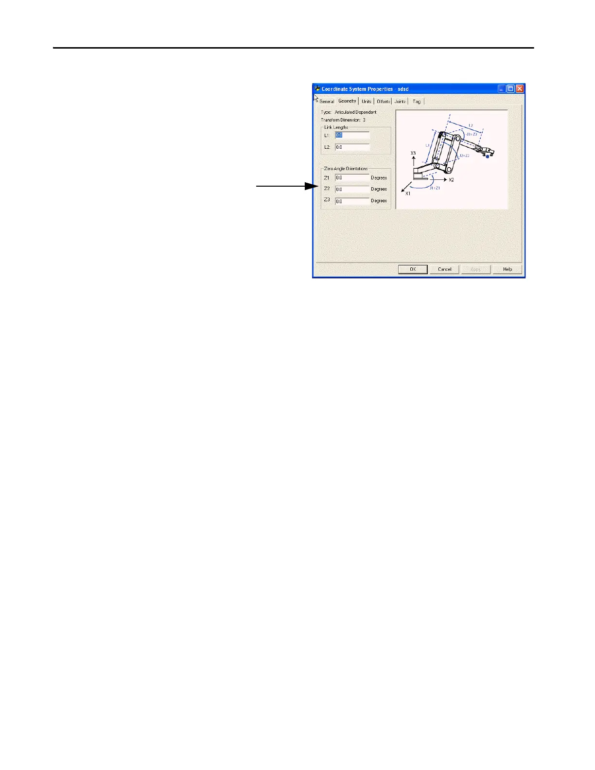
Figure 43 - Example of Zero Angle Orientation for an Articulated Dependent Robot
Method 2 - Establishing a Reference Frame
Position the robot so that:
• L1 is parallel to the X3 axis.
• L2 is parallel to X1 axis.
Program a Motion Redefine Position (MRP) instruction for all three axes to
with the following values 0, 90, and 0.
The controller automatically established the Joint-to-Cartesian reference
frame relationship after the Joint coordinate system parameters (link lengths,
base offsets, and end-effector offsets) are configured and the MCT instruction
is enabled.
Set the Zero Angle Orientations.

 Loading...


