Rockwell Automation Publication MOTION-UM002E-EN-P - June 2016 93
Configure an Articulated Dependent Robot Chapter 5
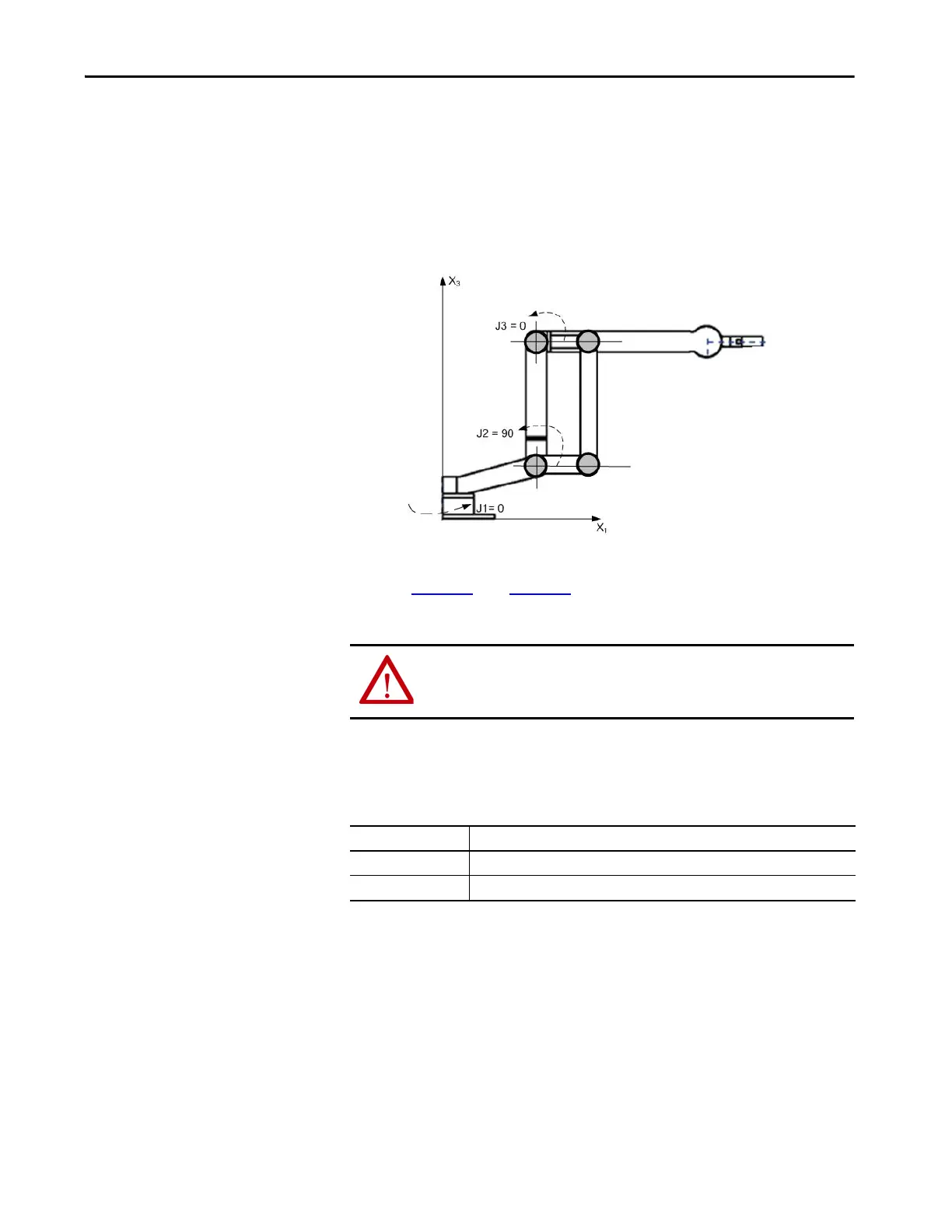
When your robot is physically in this position, the Logix Designer application
Actual Position tags for the axes must be:
•J1 = 0
• J2 = 90
•J3 = -90
Figure 42 - Articulated Dependent 3
If the physical position and joint angle values of your robot cannot match those
shown in Figure 41
or in Figure 42, use one of the methods that are outlined in
this section to establish the Joint-to-Cartesian reference frame relationship.
Methods to Establish a
Reference Frame
The following methods let you establish a reference frame for an Articulated
Independent robot.
• Method 1 - establishes a Zero Angle Orientation and lets the configured
travel limits and home position on the joint axes remain operational. Use
this method if you are operating the axes between the travel limits
determined before programming a Motion Redefine Position (MRP)
instruction and want these travel limits to stay operational.
• Method 2 - uses a Motion Redefine Position (MRP) instruction to
redefine the axes position to align with the Joint reference frame. This
method can require the soft travel limits to be adjusted to the new
reference frame.
ATTENTION: Failure to properly establish the correct reference frame for
your robot can cause the robotic arm to move to unexpected positions
potentially resulting in damage to property or injury to personnel.
For each Use one of these methods to establish the reference frame
Incremental axis Each time the power of the robot is cycled.
Absolute axis Only when you establish absolute home.

 Loading...


