Rockwell Automation Publication MOTION-UM002E-EN-P - June 2016 35
Configure a Cartesian Coordinate System Chapter 2
Bit State Diagrams for
Blended Moves
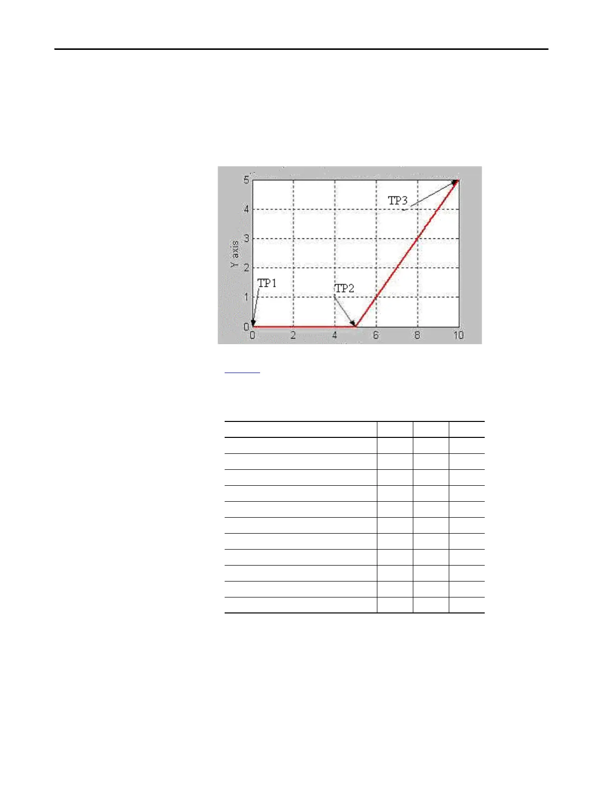
The following diagrams show bit states at the transition points for various
types of blended moves.
Bit States at Transition Points of Blended Move by Using Actual
Tolerance or No Settle
Tab le 1 0 shows the bit status at the various transition points shown in the
preceding graph with termination type of either Actual Tolerance or No Settle.
Table 10 - Bit Status at Transition Points with Actual Tolerance or No Settle Termination Type
Bit TP1 TP2 TP3
Move1.DN TTT
Move1.IP T F F
Move1.AC T F F
Move1.PC F T T
Move2.DN TTT
Move2.IP TTF
Move2.AC F T F
Move2.PC FFT
cs1.MoveTransitionStatus F F F
cs1.MovePendingStatus T F F
cs1.MovePendingQueueFullStatus T F F

 Loading...


