Rockwell Automation Publication MOTION-UM002E-EN-P - June 2016 23
Create and Configure a Coordinate System Chapter 1
Axis Grid
The Axis Grid of the Units dialog box displays the axis names that are
associated with the coordinate system, the conversion ratio, and the units that
are used to measure the conversion ratio.
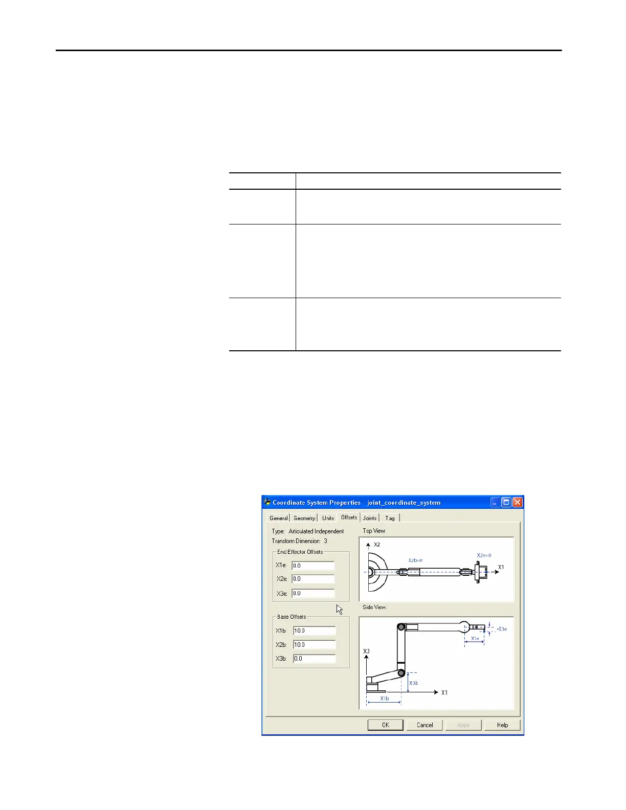
Offsets Tab
The Offsets tab of the Coordinate System Properties dialog box is where you
define the end effector and base offset values for the robotic arm. This tab
shows the top and/or sides view of a typical robotic arm, based on the type of
coordinate system and coordinate Transform dimension values specified on the
General tab. The number of axes associated with the coordinate system
determines the number of available offset fields in each box.
Table 4 - Units Tab Description
Item Description
Axis Name The Axis Name column contains the names of the axes assigned to the coordinate system in
the General dialog box. These names appear in the order that they were configured into the
current coordinate system. You cannot edit this column from this dialog box.
Conversion Ratio The Conversion Ratio column defines the relationship of axis position units to coordination
units for each axis. For example, there is a program the position units for an axis are in
millimeters and the axis is associated with a coordinate system whose units are in inches.
The conversion ratio for this axis/coordinate system association is 25.4/1 and can be
specified in the appropriate row of the Axis Grid.
The numerator can be entered as a float or an integer. The denominator must be entered
only as an integer.
Conversion Ratio
Units
The Conversion Ratio Units column displays the axis position units to coordination units
used. The Axis Position units are defined in the Axis Properties – Units dialog box and the
coordination units are defined in Coordinated System Properties – Units dialog box. These
values are dynamically updated when changes are made to either axis position units or
coordination units.

 Loading...


