Rockwell Automation Publication MOTION-UM002E-EN-P - June 2016 67
Configure an Articulated Independent Robot Chapter 4
Identify the Work Envelope for a Delta Three-dimensional Robot
The work envelope is the three-dimensional region of space that defines the
reaching boundaries for the robot arm. The typical work envelope for a Delta
robot can be described as looking similar to plane in the upper region, with
sides similar to a hexagonal prism and the lower portion similar to a sphere. For
more detailed information regarding the work envelope of your Delta three-
dimensional robot, see the documentation provided by the robot
manufacturer.
We recommend that you program the robot within a rectangular solid defined
inside the robots work zone. The rectangular solid can be defined by the
positive and negative dimensions of the X1, X2, X3 virtual source axes. Be sure
that the robot position does not go outside the rectangular solid. You can
check the position in the event task.
To avoid issues with singularity positions, Logix Designer application
internally calculates the joint limits for the Delta robot geometries. When an
MCT instruction is invoked for the first time, the maximum positive and
maximum negative joint limits are internally calculated based upon the link
lengths and offset values entered on the Geometry and Offsets tabs of the
Coordinate System Properties dialog.
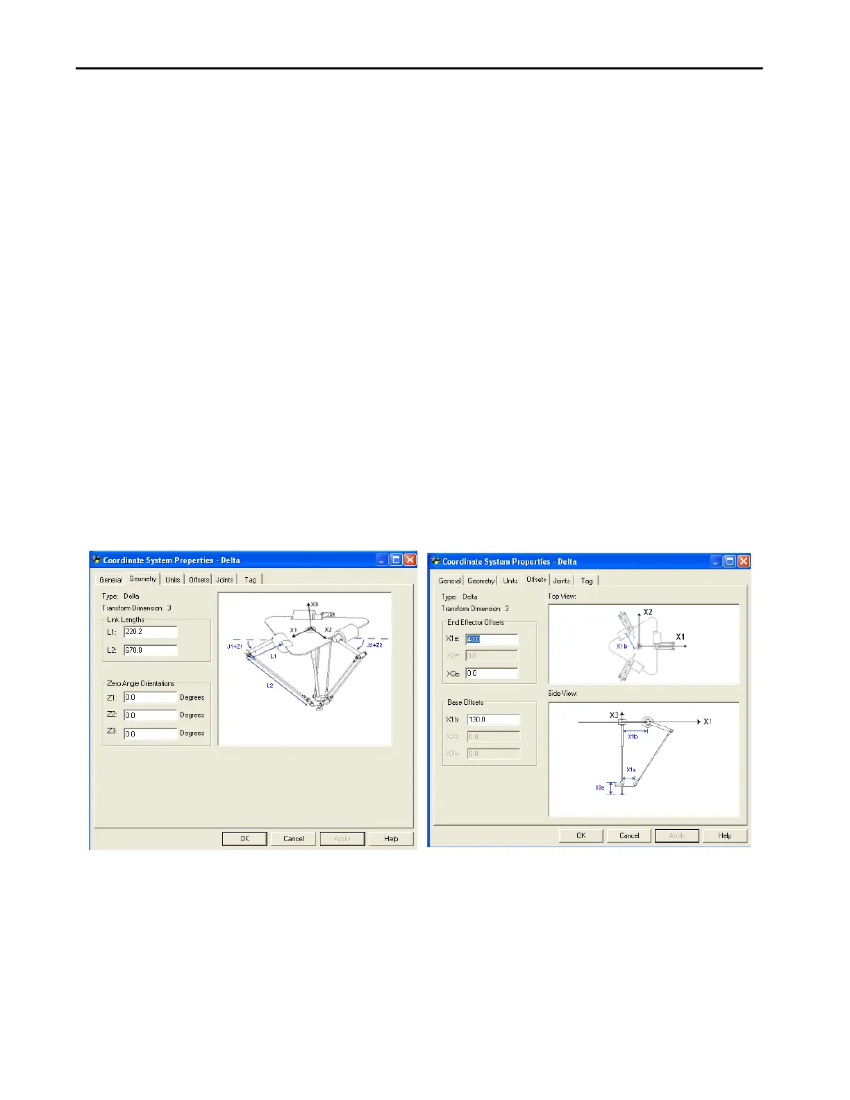
Figure 20 - Delta Three-dimensional Configuration Systems Properties Dialog - Geometry and
Offsets Tabs
During each scan, Logix Designer application evaluates the joint positions in
the forward and inverse kinematics routines to be sure that they do not violate
the computed maximum positive and maximum negative joint limits.

 Loading...


