Parameters
84 M-Max Series Adjustable Frequency Drive MN04020003E—October 2013 www.eaton.com
Drives Control, continued
S-Formed Curve for Acceleration and Deceleration Ramps
PNU ID
Access
RUN Value/Range Description
Factory Setting
(P1.3)
P6.7 505 X — Start function 0
0 Ramp (acceleration)
The acceleration time with the value set at parameter P6.5
1 Flying restart circuit
Starting on a running motor. By switching on a small current
value, a small torque is created
With a frequency search (beginning with the maximum
frequency P6.4), the correct rotational field frequency is
determined. The output frequency is then adapted to the
specified setpoint frequency based on the defined acceleration
(P6.5) and deceleration (P6.6) times
Use this function if, for instance, the motor is already turning at
the start command, with flow-machines (pumps, fans) and
with short interruptions in input voltage
P6.8 506 X — Stop function 0
0 Free coasting
The motor carries out an uncontrolled stop (coasting) after
the start enable (FWD/REV) is switched off or when the STOP
button (P6.16) is actuated
1 Ramp (deceleration) = dynamic braking
Deceleration time with the value set under P6.6
If the energy that is fed back by the motor during the dynamic
braking is too high, the deceleration time has to be extended.
On devices with internal braking transistors, the excess energy
can be dispelled through an external braking resistance
(optional) (see “Braking (P12)” on Page 112)
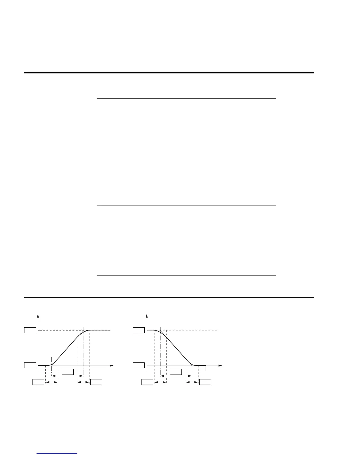
P6.9 500 X — S ramp 0.0
0.0 Linear acceleration and deceleration time based on P6.5
and P6.6
0.1–10.0s Time-graded transition to start and end of the acceleration
ramp (P6.5) and deceleration ramp (P6.6)
The time set here applies for both ramps (see figure below)
f
P6.4
P6.3
P6.9 P6.9
t
P6.5
P6.4
P6.3
P6.6
P6.9P6.9
f
t
 Loading...


