Appendix A
M-Max Series Adjustable Frequency Drive MN04020003E—October 2013 www.eaton.com 145
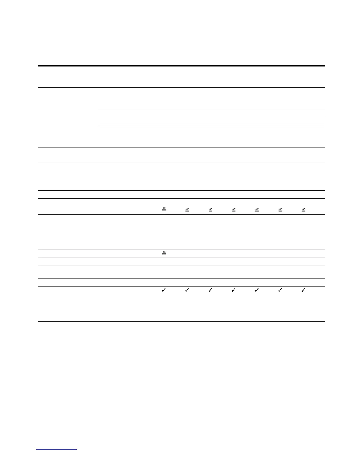
Device Series MMX34
Notes
Symbols used in technical data and formulas.
Guide value (calculated), no standard rating.
MMX34AA…FO-O Symbols
Unit 1D3 1D9 2D4 3D3 4D3 5D6 7D6
Rated operational current (I
e
)I
e
A 1.3 1.9 2.4 3.3 4.3 5.6 7.6
Overload current for 60s every
600s at 122°F (50°C)
I
L
A 2 2.9 3.6 5 6.5 8.4 11.4
Starting current for 2s
every 20s at 122°F (50°C)
I
L
A 2.6 3.8 4.8 6.6 8.6 11.2 15.2
Apparent power in rated
operation
400V S kVA 0.9 1.32 1.66 2.29 2.98 3.88 5.27
480V S kVA 1.08 1.56 2 2.74 3.57 4.66 6.32
Assigned motor rating 400V P kW 0.37 0.55 0.75 1.1 1.5 2.2 3
460V HP 1/2 3/4 1 1-1/2 2 3 4
Power side (Primary side)
Number of phases Three-phase
Rated voltage U
LN
V 380V –15%–480V +10%, 50/60 Hz
(323–528V ±0%, 45–66 Hz ±0%)
Input current I
LN
A 2.2 2.8 3.2 4 5.6 7.3 9.6
Maximum leakage current to
ground (PE) without motor
MMX34...N_ I
PE
mA
MMX34...F_ I
PE
mA 45.1 45.1 45.1 25.1 25.1 25.1 24.9
Braking torque
Default I/I
e
%30
30 30 30 30 30 30
Brake chopper with external
braking resistance
— — — Max. 100% rated operational current I
e
with
external braking resistance
Minimum braking resistance R
B
ohms ———7575 75 54
Switch-on threshold for the
braking transistor
U
DC
Vdc — — — Programmable P12.6
DC braking I/I
e
% 100, adjustable
Pulse frequency f
PWM
kHz 6 (adjustable 1–16)
Heat dissipation at rated
operational current (I
e
)
P
v
W 21.7 29.7 31.7 51.5 66.4 88.3 116.9
Efficiency h 0.94 0.95 0.95 0.95 0.96 0.96 0.96
Fan (device-internal,
temperature-controlled)
Installation size FS1 FS1 FS1 FS2 FS2 FS2 FS3
Weight m Lbs
(kg)
1.2
(0.55)
1.2
(0.55)
1.2 (
0.55)
1.5
(0.7)
1.5
(0.7)
1.5
(0.7)
2.2
(0.99)
 Loading...


