Parameters
104 M-Max Series Adjustable Frequency Drive MN04020003E—October 2013 www.eaton.com
Example A
P10.9 = 1: Execute program cycle once.
P10.10 = 0 (see Page 102): The fixed frequencies FF0 to FF7
(P10.1–P10.8) are set in numerical order with the associated
run times (P10.10–P10.18) and rotating direction (FWD) as
setpoint.
The start command (RUN) for the sequence control is set via
the digital input (DI1–DI6) defined at parameter P3.21. It has
a higher priority than other start commands. This also applies
to the fixed frequency setpoints of the sequence control
compared to setpoint sources.
WARNING
If a start command is present at a digital input (DI1–DI6)
assigned at P3.21, the sequence control also starts
automatically (without switch edge) when the power
supply is switched on (for example, after a power supply
failure).
If the start command (RUN) is switched off during the
program cycle, the drive stops according to the settings at
P6.8. The program sequence is then ended immediately. A
renewed start command begins once more with the first
fixed frequency.
A digital input (DI1–DI6) can be assigned the “Pause
sequence control” function at parameter 3.22. The program
sequence is then stopped and can then be resumed from
this stopping point (fixed frequency).
The operating states of the sequence control can be
displayed via the digital outputs RO1, RO2 and DO.
The following assignments are shown in example A:
●
Relay RO1 (P5.1 = 16) signals the operation (RUN) of
the sequence control. It switches on with the start
command and then off after one completed program cycle
(P10.9 = 1, P10.9 = 3) at the end of the program cycle
(P5.3 = 18)
●
[1] With a continuous program sequence (P10.9 = 2,
P10.9 = 4), the start signal is switched off first (P3.21)
●
Relay RO2 (P5.2 = 17) indicates the end of the individual
run times (P10.11–P10.18)
●
Transistor DO (P5.3 = 18) indicates the end of a program
cycle
Value 19 (for example, P5.3 = 19) enables a pause command
(P3.22) of the sequencing control to be indicated via a digital
output.
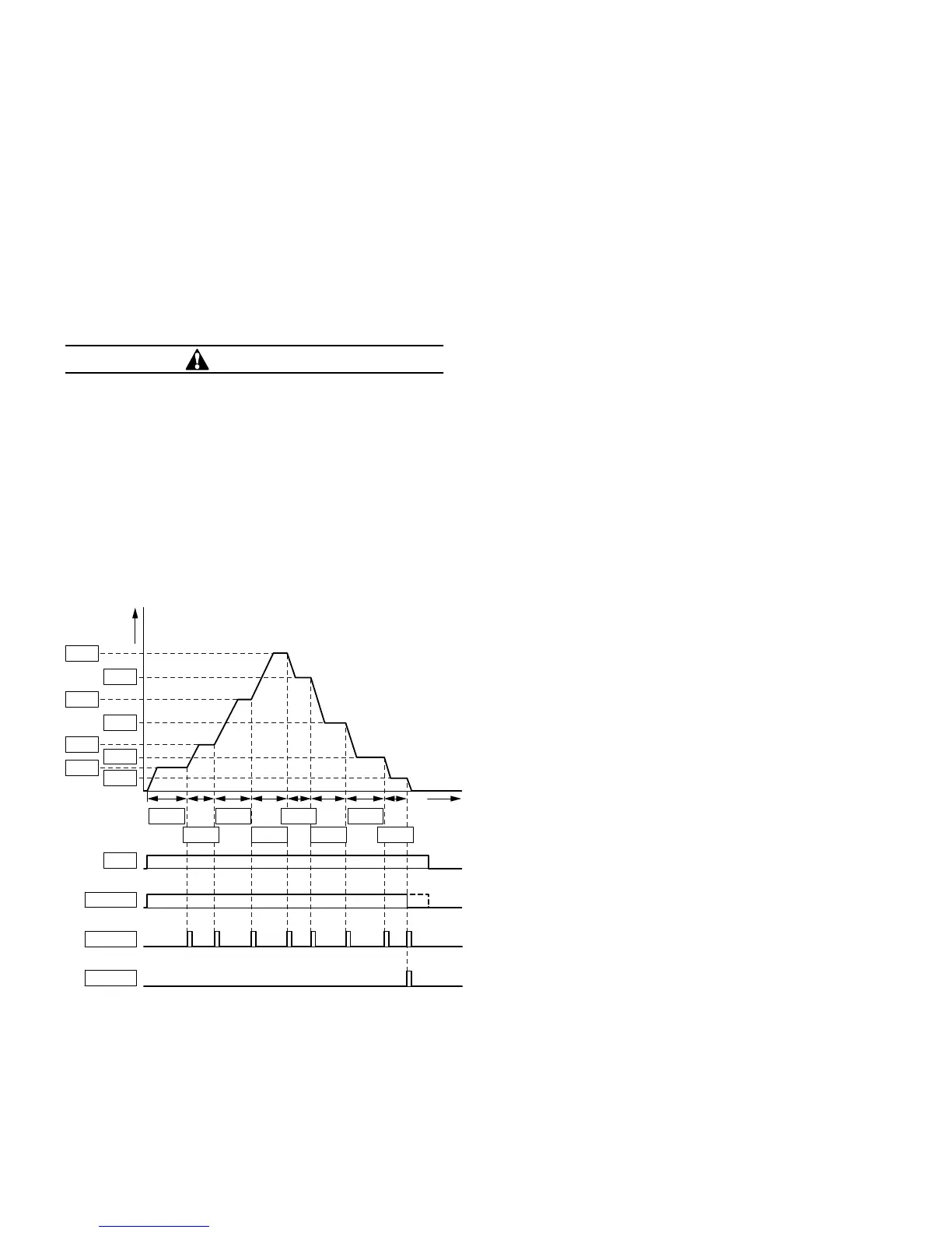
Example A, Program Cycle Executed Once (P10.9 = 1, P10.10 = 0)
P10.6
P10.5
P10.4
P10.7
P10.8
P3.21
P10.17
P10.18
P10.15
P10.16
P10.13
P10.14
P10.11
P10.12
f
(Hz)
FWD
P5.3 = 18
P5.2 = 17
P5.1 = 16
P10.3
P10.2
P10.1
t
1
 Loading...


