Engineering
M-Max Series Adjustable Frequency Drive MN04020003E—October 2013 www.eaton.com 19
Electrical Power Network
Input Connection and Configuration
The M-Max series frequency inverters can be connected and
operated with all control-point grounded AC power networks
(see IEC 60364 for more information).
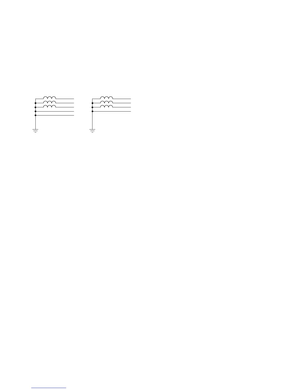
AC Power Networks with Grounded Center Point
(TN-/TT Networks)
While planning the project, consider a symmetrical
distribution to the three external conductors, if multiple
frequency inverters with single-phase supplies are to be
connected. The total current of all single-phase consumers is
not to cause an overload of the neutral conductor
(N-conductor).
The connection and operation of frequency inverters to
asymmetrically grounded TN networks (phase-grounded
Delta network “Grounded Delta”, USA) or non-grounded or
high-resistance grounded (over 30 ohms) IT networks is only
conditionally permissible.
If the M-Max frequency inverters are connected to an
asymmetrically grounded network or to an IT network
(non-grounded, insulated), the internal interference
suppression filter must be disconnected (unscrew the screw
marked EMC, see “Electrical Installation” on Page 32). The
required filtering for electromagnetic compatibility (EMC) is
then no longer present.
Measures for electromagnetic compatibility are mandatory in
a drive system in order to meet the legal requirements for
EMC and low voltage regulations.
Good grounding measures are a prerequisite for the effective
insert of further measures such as shielding or filters.
Without respective grounding measures, further steps are
superfluous.
Input Voltage and Frequency
The standardized input voltages (IEC 60038, VDE017-1) for
energy suppliers (EVU) guarantee the following conditions at
the transition points:
●
Deviation from the rated value of voltage: maximum ±10%
●
Deviation in voltage phase balance: maximum ±3%
●
Deviation from rated value of the frequency:
maximum ±4%
The broad tolerance band of the M-Max frequency inverter
considers the rated value for
European as (EU: U
LN
= 230V/400V, 50 Hz) and
American as (USA: U
LN
= 240V/480V, 60 Hz) standard
voltages:
●
120V, 50/60 Hz at MMX11
●
230V, 50 Hz (EU) and 240V, 60 Hz (USA) at MMX12 and
MMX32
●
400V, 50 Hz (EU) and 480V, 60 Hz (USA) at MMX34_
●
575V, 50 Hz (EU) and 575V, 60 Hz (USA) at MMX35_
For the bottom voltage value, the permitted voltage drop of
4% in the consumer circuits is also taken into account.
●
100V device class (MMX11):
110V –15% to 120V +10% (94V –0% to 132V +0%)
●
200V device class (MMX12, MMX32):
208V –15% to 240V +10% (177V –0% to 264V +0%)
●
400V device class (MMX34):
380V –15% to 480V +10% (323V –0% to 528V +0%)
●
575V device class (MMX35):
575V –15% to 575V +10% (489V – 0% to 632.5V +0%)
The permitted frequency range is 50/60 Hz (45 Hz –0%
–66 Hz +0%).
L2
N
L1
L3
PE
L2
PEN
L1
L3
 Loading...


