Parameters
M-Max Series Adjustable Frequency Drive MN04020003E—October 2013 www.eaton.com 77
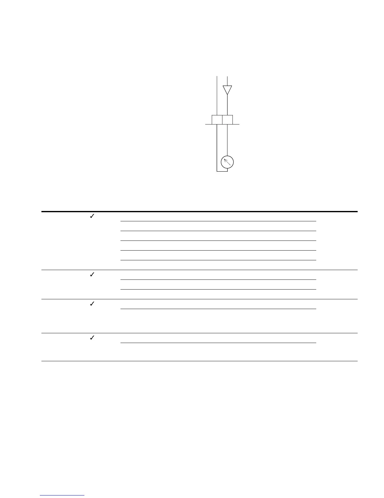
Analog Outputs (P4)
An analog voltage signal from 0–10V is output at control
signal terminal 18. The maximum permissible load is 10 mA.
Reference potential is GND on control signal terminals 3
and 5.
In the factory setting, the voltage signal (0–10V) is
proportional to the output frequency f-Out = 0–f
max
(P6.4).
The output signal is not monitored by the frequency inverter.
Analog Output AO
Analog Outputs
5
0–10V
AO
18
GND
<10 mA
f-Out
–
+
PNU ID
Access
RUN Value/Range Description
Factory Setting
(P1.3)
P4.1 307 — AO signal (Analog Output) 1
0 Deactivated
1 Output frequency f-Out = 0–f
max
(P6.4)
2 Output current I
2
= 0–I
N Motor
(P7.1)
3 Torque M
N
= 0–100% (calculated value)
4 PID controller, output (0–100%)
P4.2 310 — AO, minimum value 1
00V
1 2V (live-zero)
P4.3 1456 — AO, gain 100.00
0.00–200.00% Gain factor
The maximum value set here always corresponds to the
maximum output voltage 10V
P4.4 1477 — AO, filter time 0.10
0.00–10.00s Filter time constant for the analog output voltage
See “Filter Time Constant” on Page 70
 Loading...


