Parameters
M-Max Series Adjustable Frequency Drive MN04020003E—October 2013 www.eaton.com 71
Digital Inputs (P3)
The parameter group P3 is used to set the operation and function of the digital inputs
DI1 to DI6.
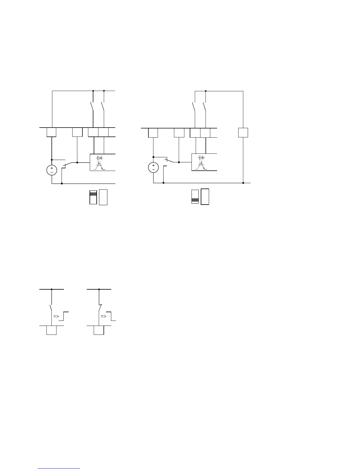
Digital Inputs for Source and Sink Type
Source type (LOGIC+) = switch at the voltage source. All
digital inputs are connected to the voltage sink via
microswitch S1 (0V = reference potential GND).
Sink type (LOGIC–) = switch at the voltage sink
(0V = reference potential GND). All digital inputs are
connected to the voltage source via microswitch S1.
Both switch types ensure failsafe actuation.
Control Logic Reaction to a Rising or Falling Edge
(Source Type, Sink Type)
In the factory setting, the operation of the M-Max is active
via control signal terminals (I/O) with LOGIC+ (Source type):
●
DI1 (control signal terminal 8): FWD (Forward = Start
enable clockwise rotating field)
●
DI2 (control signal terminal 9): REV (Reverse = Start enable
anti-clockwise rotating field)
●
DI3 (control signal terminal 10): FF1 (fixed frequency
1 = 10 Hz)
●
DI4 (control signal terminal 14): FF2 (fixed frequency
2 = 15 Hz)
●
DI5 (control signal terminal 15): Reset (acknowledge error
message ALARM)
●
DI6 (control signal terminal 16): PID-Off (lock of the PID
controller)
The joint actuation of control signal terminal 10 (FF1) and
control signal terminal 14 (FF2) activates the fixed frequency
FF3 (20 Hz) in the factory setting.
The individual digital inputs (D_) can be assigned several
functions. The assigned functions are activated if, with
LOGIC+, the control signal terminal is actuated with +24V
(rising edge, failsafe).
789
DI1
DI2
DI_COM
S1
24V
6
<50 mA
+24V Out
S1 = LOGIC+
(Source Type)
LOGIC
– +
789
DI1
DI2
DI_COM
S1
6
<50 mA
+24V Out
S1 = LOGIC–
(Sink Type)
LOGIC
– +
5
GND
DI1
8
DI1
8
 Loading...


