Parameters
124 M-Max Series Adjustable Frequency Drive MN04020003E—October 2013 www.eaton.com
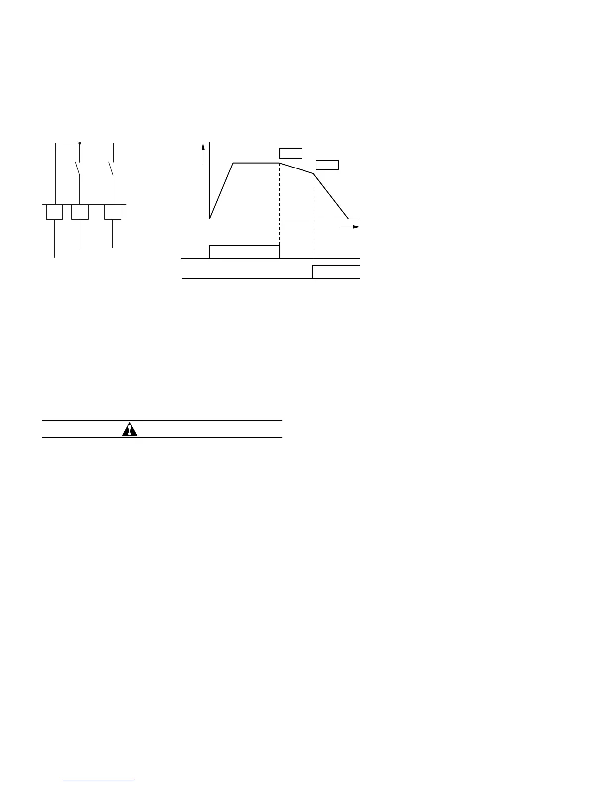
Example 2
Stop function with two different deceleration times.
Stop Function with Two Different Deceleration Times
The Stop function with deceleration time can be activated
with parameter P6.8 = 1. If the enable signal on the digital
input DI1 (FWD, control signal terminal 8) is switched off, the
output frequency of the frequency inverter can be reduced
according to the deceleration time (dec1) set at P6.6.
The second parameter set (2PS) enables you to set at P14.10
a different value to dec1 or dec2. For example, the second
parameter set (P14) is activated here via digital input DI6
(P3.27 = 6). Activating DI6 causes the output frequency to be
reduced according to the deceleration time (dec3) set at
P14.10.
CAUTION
Debounced inputs may not be used in the safety circuit
diagram.
The motor parameters must be identical in both parameter
groups (P7 and P14).
Digital input 6 is assigned in the factory setting (P3.12 = 6)
with the function PI-OFF (PID controller, deactivated). With
P3.12 = 0 you can remove this function (PI-OFF) from digital
input 6.
8
DI1
DI6
16
FWD
2PS
24V
6
<50 mA
+24V Out
f
t
P6.6
P14.10
FWD
2PS
 Loading...


