Parameters
M-Max Series Adjustable Frequency Drive MN04020003E—October 2013 www.eaton.com 61
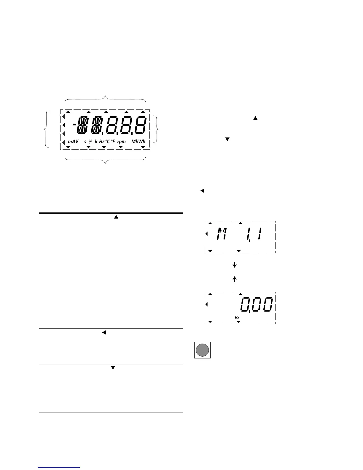
Display Unit
The following shows the display unit (LCD display with all
display elements).
LCD Display (Areas)
The display unit consists of a backlit liquid crystal display
(LCD). It is divided into four areas.
Areas of the LCD Display
General Information on Menu Navigation
By applying the specified supply voltage to the connection
terminals L2/N and L3 (MMX11), L1 and L2/N (MMX12) or
L1, L2/N and L3 (MMX32, MMX34), the frequency inverter
automatically runs the following functions:
●
The lighting of the LCD display is switched on and all
segments are actuated briefly
●
After the self-test, the top status line of the LCD display
indicates that the device is ready to start and proper
operation by an arrow under READY. The arrow under
STOP indicates that there is no start command (FWD or
REV)
●
The arrow in the bottom status line shows the actuation
via control signal terminals with the factory setting on I/O
Control (Control Input/Output). The arrow over FWD
(Forward) indicates the basic rotational direction (phase
sequence for a clockwise rotating field) on the output
terminals U/T1, V/T2 and W/T3)
●
Display for the operating data M1.1 and 0.00 Hz (output
frequency) in automatic alternating sequence. The arrow
in the left-hand status line indicates menu level MON
(Monitor = Operating data display)
Operational Data Indicator (Operational)
The frequency inverter is ready for operation and can be
started via the control signal terminal with the specified
values from the factory settings when connecting the
allocated motor output (see “Commissioning with Control
Signal Terminals (Factory Setting)” on Page 52).
Area Description
1 Status
indicator
The arrowheads ( ) on the top border show
information regarding the drive:
READY = Ready to start
RUN = Operating notification
STOP = Stop, stop command activated
ALARM = Alarm message activated
FAULT = The drive has been stopped due to an error
message
2 Plain text
display
Two 14- and three 7-segment blocks for displaying:
AL = Alarm message
F = Error messages
M = Measurement value (operating data)
P = Parameter numbers
S = System parameter
- = Anticlockwise field of rotation (REV)
The respective units of measurement are displayed in
the bottom line
3 Menu level The arrow shows the selected main menu:
REF = Reference value input (reference)
MON = Operational data indicator (monitor)
PAR = Parameter levels
FLT = Fault log (Fault)
4 Control
commands
The arrowhead points to the selected rotating field
direction and the active control level:
FWD = Clockwise rotating field (forward run)
REV = Counterclockwise rotating field (reverse run)
I/O = Via control terminals (input/output)
KEYPAD = Via control unit
BUS = Via fieldbus (interface)
RUN STOP ALARM FAULTREADY
REF
FWD REV I/O KEYPAD BUS
MON
PAR
FLT
1
4
23
By actuating the OK button, you can set the
alternating display mode to stay on the output
frequency (0.00 Hz).
RUN STOP ALARM FAULTREADY
REF
FWD REV I/O KEYPAD BUS
MON
PAR
FLT
Display in Automatic Alternation
RUN STOP ALARM FAULTREADY
REF
FWD REV I/O KEYPAD BUS
MON
PAR
FLT
OK
 Loading...


