Installation
38 M-Max Series Adjustable Frequency Drive MN04020003E—October 2013 www.eaton.com
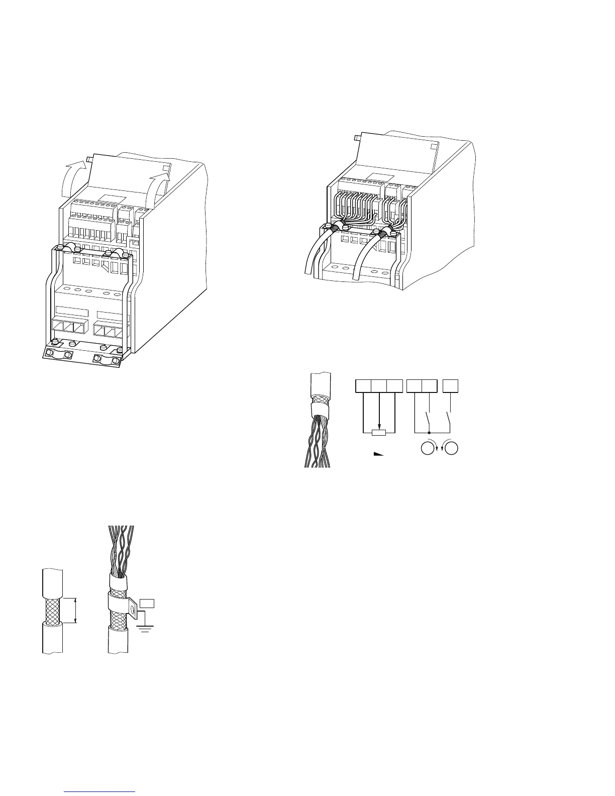
Connection on Control Section
The control signal terminals are arranged under the front
cover flap.
Position of Control Signal Terminals
The cable hold down clamps contained in the scope of
delivery can be mounted on the cable clamp plate of the
power section.
The control lines should be shielded and twisted. The
shielding is exposed on one side (PES), on the cable hold
down clamps on the frequency inverter for instance.
Prevent the shielding from becoming unbraided, for example,
by pushing the separated plastic covering over the end of the
shielding or with a rubber grommet on the end of the
shielding.
Prevent the Shield from Becoming Unbraided
As an alternative, in addition to a broad area cable clip, you
can also twist the shielding braid at the end and connect to
protective ground with a cable clip. To prevent EMC
disturbance, this twisted shielding connection should be
made as short as possible (see figure on Page 35).
Example for a Single-Side Connection (PES) to the
Frequency Inverter
Prevent any unraveling on the other end of the control line
with a rubber grommet. The shielding braid is not to make
any connection with protective ground here because this
would cause problems with an interference loop.
Example for an Insulated End of the Control Cable
L1 L2/N L3
U/T1
V/T2
W/T3
0.59 in
(15 mm)
PES
1
+10V AI1 GND 24V DI1 DI2
23 68 9
4K7
M
R11
M
FWD
REV
 Loading...


