Appendix A
142 M-Max Series Adjustable Frequency Drive MN04020003E—October 2013 www.eaton.com
Appendix A
Special Technical Data
The following tables show the technical data of the M-Max frequency inverter in the individual
power classes with the allocated motor output.
The motor output allocation is based on the rated operational current.
The motor output designates the respective active power output to the drive shaft of a
normal, four-pole, internally or externally ventilated three-phase asynchronous motor with
1.500 RPM at 50 Hz or 1.800 RPM at 60 Hz.
Device Series MMX11
Notes
Symbols used in technical data and formulas.
Internal voltage doubler circuit:
U
LN
= 115V U
2
= 230V
U
LN
= 120V U
2
= 240V
Guide value (calculated), no standard rating.
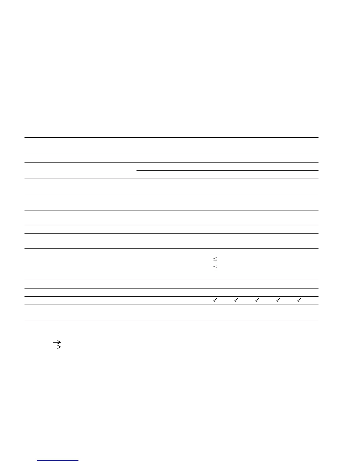
MMX11AA…NO-O Symbols
Unit 1D7 2D4 2D8 3D7 4D8
Rated operational current I
e
A 1.7 2.4 2.8 3.7 4.8
Overload current for 60s every 600s at 122°F (50°C) I
L
A 2.6 3.6 4.2 5.6 7.2
Starting current for 2s every 20s at 122°F (50°C) I
L
A 3.4 4.8 5.6 7.4 9.6
Apparent power at rated operation
230V S kVA 0.68 0.96 1.12 1.47 1.91
240V S kVA 0.71 0.99 1.16 1.54 1.99
Assigned motor rating (230V)
P kW 0.25 0.37 0.55 0.75 1.1
HP 1/4 1/2 3/4 1 1-1/2
Power side (primary side)
Number of phases Single-phase or two-phase
Rated voltage
U
LN
V 110 –15%–120 +10%, 50/60 Hz
(94–132V ±0%, 45–66 Hz ±0%)
Input current I
LN
A 9.2 11.6 12.4 15 16.5
Maximum leakage current to ground (PE) without motor
MMX11...N_ I
PE
mA
Braking torque
Default M/M
N
% 30
DC braking I/I
e
% 100, adjustable
Pulse frequency f
PWM
kHz 6 (adjustable 1–16)
Heat dissipation at rated operational current (I
e
)P
v
W 22.3 27.9 33.4 40.3 49.2
Efficiency h 0.91 0.92 0.94 0.95 0.96
Fan (device-internal, temperature-controlled)
Installation size FS2 FS2 FS2 FS2 FS3
Weight m Lbs (kg) 1.5 (0.7) 1.5 (0.7) 1.5 (0.7) 1.5 (0.7) 2.2 (0.99)
 Loading...


