Parameters
68 M-Max Series Adjustable Frequency Drive MN04020003E—October 2013 www.eaton.com
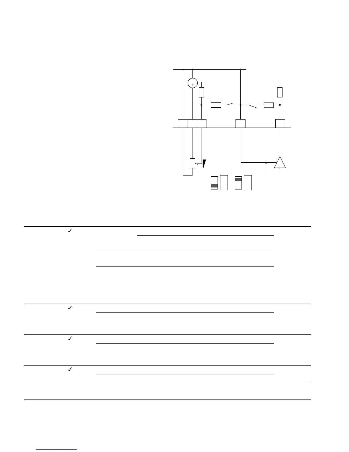
Analog Input (P2)
In parameter group P2, you can adapt the analog inputs:
The signal range depends on the switch position of the
microswitches (see figure on this page):
●
S2 = V: AI1 (control signal terminal 2), voltage signal
0/2 – +10V
●
S3 = mA: AI2 (control signal terminal 4), current signal
0/4 – 20 mA
Reference potential for the analog inputs (AI1, AI2) is GND
(control signal terminals 3 and 5).
The allocation of the analog inputs (AI1, AI2) can be set under
parameter P6.2 and P6.18 (setpoint input) as well as P9.5
and P9.6 (PI controller, actual value).
Analog Inputs AI1 and AI2
Analog Inputs
12354
0 (4)–20 mA
AI1
GND
<10 mA
+10V Out
S3S2
GND
0–10V
200k ohms 200k ohms
200 ohms
200 ohms
AI2
PI-Ist
f-Soll
S2 = AI1V
(0–10V)
AI1
V mA
S3 = AI2 mA
(4–20 mA)
AI1
V mA
PNU ID
Access
RUN Value/Range Description
Factory Setting
(P1.3)
P2.1 379 — AI1 signal range (analog input) 0
Depending on the switch position of microswitch S2
(FS = frequency setpoint)
0 S2 = V: 0–10V, voltage signal (FS, see P6.2)
S2 = mA: 0–20 mA, current signal
1 With live-zero,
S2 = V: 2–10V, voltage signal
S2 = mA: 4–20 mA, current signal
At P8.1 it is possible to set the response of the MMX
to a setpoint error (life zero)
P2.2 380 — AI1 custom minimum 0.00
–100.00% to
100.00%
Scaling of the analog input signal (V/mA) in the zero range
(minimum response value)
See “Scaled Value Range (AI1, AI2)” on Page 69
P2.3 381 — AI1 custom maximum 100.00
–100.00% to
100.00%
Scaling of the analog input signal (V/mA) in the limit value
range (highest limit value)
See “Scaled Value Range (AI1, AI2)” on Page 69
P2.4 378 — AI1, filter time 0.1
0.0 No filter function
0.1–10s Filter time constant for the analog input signal (V/mA)
See“Filter Time Constant” on Page 70
 Loading...


