Parameters
M-Max Series Adjustable Frequency Drive MN04020003E—October 2013 www.eaton.com 127
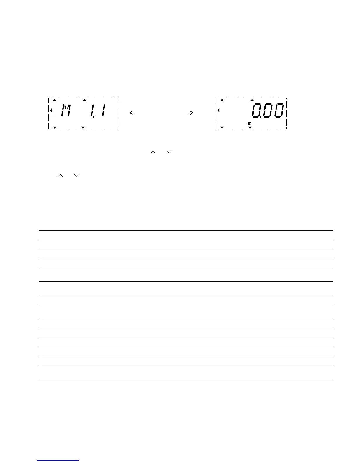
Operational Data Indicator (MON)
By applying the specified supply voltage (L1, L2/N, L3), the LCD display is illuminated
(= Power ON) and all segments are shown briefly. The parameter number (M1.1) and the
respective display value (0.00) are then displayed automatically in alternating sequence.
Operational Data Indicator
You can use the MON (Monitor) menu level to select the desired operational data indicator
(parameter number M_) with the arrow buttons and . The parameter number and the
display value are shown in alternation automatically, and the display can be fixed on the
selected display value with the OK button. If you wish to access a different operational data
indicator, press the OK button once again. You can then make the selection with the arrow
buttons and and confirm with the OK button. The appropriate unit is shown under the
respective operational data indicator.
The values of the operating data display cannot be changed by hand (i.e. by value entry).
You can select operational data indicators during operation (RUN).
Operational Data Indicator
Notes
The calculated motor data (M1.3, M1.5 and M1.6) is based on the values entered in parameter group P7
(see “Motor (P7)” on Page 88
).
The calculated motor temperature (M1.10) considers the temperature model of the protection function in parameter group P8
(see “Protective Functions (P8)” on Page 90).
PNU ID Designation
Display
Value Unit Description
M1.1 1 Output frequency 0.00 Hz Frequency to motor
M1.2 25 Frequency reference value 0.00 Hz Frequency reference value
M1.3 2 Motor shaft speed 0 RPM Calculated speed of the motor (RPM)
M1.4 3 Motor current 0.00 A Measured motor current
M1.5 4 Motor torque 0.0 % Calculated ratio of torque to rated torque of the
motor
M1.6 5 Motor power 0.0 % Calculated ratio of actual output power to rated
motor output
M1.7 6 Motor voltage 0.0 V Measured output voltage to motor
M1.8 7 DC bus voltage 000 V Measured intermediate circuit voltage
(depending on the supply voltage)
M1.9 8 Unit temperature 00 °F (°C) Measured heat sink temperature
M1.10 9 Motor temperature 0 % % (calculated value)
M1.11 13 Analog input 1 0.0 % Value on AI1
M1.12 14 Analog input 2 0.0 % Value on AI2
M1.13 26 Analog output 1 0.0 % Value on AO1
M1.14 15 Digital input 0 — Status DI1, DI2, DI3 (see “Example of Status
Displays” on Page 128)
RUN STOP ALARM FAULTREADY
REF
FWD REV I/O KEYPAD BUS
MON
PAR
FLT
RUN STOP ALARM FAULTREADY
REF
FWD REV I/O KEYPAD BUS
MON
PAR
FLT
Display in automatic
 Loading...


