Serial Interface (Modbus RTU)
M-Max Series Adjustable Frequency Drive MN04020003E—October 2013 www.eaton.com 133
For Modbus to function at least the following parameters must be set:
Another requirement is that the arrow in the lower status line of the LCD display is pointing
to BUS (adjustable via the LOC/REM button). The PLC (master) must also be provided with an
RS485 serial interface and the necessary Modbus RTU driver software.
Operating Mode Modbus RTU
Operating mode Modbus RTU (Remote Terminal Unit) transfers the data in binary
format (faster data rate) and determines the transfer format for the data request and the
data response. Each message byte that is sent contains two hexadecimal characters
(0 … 9, A … F).
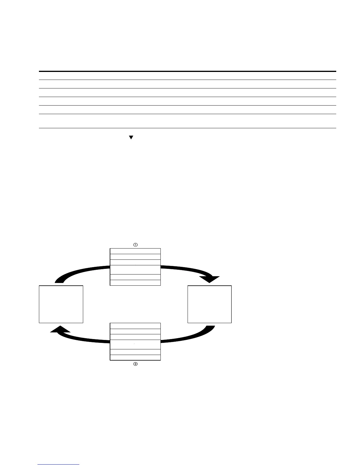
The data transfer between a master (PLC) and the frequency inverter (M-Max) is carried out
according to the following sequence:
Master request: the master sends a Modbus frame to the frequency inverter.
Slave response: the frequency inverter sends a Modbus frame as a response to the master.
Data Exchange Between Master and Slave
The frequency inverter (slave) only sends a response if it has received a request from the
master beforehand.
Notes
Master request.
Slave response, not with broadcast.
PNU Value Notes
S2.2 1 To activate Modbus
S2.3 1–255 Set differently at each slave (MMX); 0 is used by the master for broadcasts
S2.4 0–8 Same setting at the master and slave
S2.6 0/1 Same setting at the master and slave
6.1 3 Fieldbus selected as a control level
6.2 2 Set setpoint value via the fieldbus; other setpoint sources also possible, fixed frequencies overlay all
setpoint values, also a fieldbus setpoint value
Start
Master
Address (1 Byte)
Function Code (1 Byte)
Data (N x 1 Byte)
CRC (2 Bytes)
End
Start
Address (1 Byte)
Function Code (1 Byte)
Data (N x 1 Byte)
CRC (2 Bytes)
End
(Slave)MMX_
 Loading...


