Parameters
M-Max Series Adjustable Frequency Drive MN04020003E—October 2013 www.eaton.com 83
Drives Control, continued
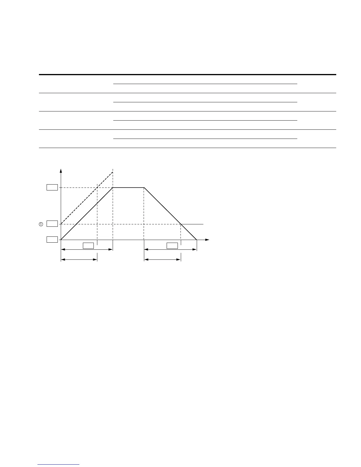
Acceleration and Deceleration Time
The values for the acceleration time t
1
and the deceleration time t
2
are calculated as follows:
The defined acceleration (P6.5) and deceleration times (P6.6) apply for all changes to the
frequency setpoint value.
If the start-release (FWD, REV) is switched off, the output frequency (f
Out
) is immediately set
to zero. The motor runs down uncontrolled.
If a controlled run-down is requested (with value from P6.6), parameter P6.8 must be 1.
Starting friction and load inertia can lead to longer acceleration times for the drive than are set
in P6.5. Large centrifugal masses or if driven by the load, the deceleration time of the drive
can be greater than is set in P6.6.
Notes
When setting a minimum output frequency (P6.3 greater than 0 Hz), the acceleration and deceleration time of the
drive is reduced to t
1
or t
2
.
Reference points for the acceleration and deceleration times set in parameters P6.5 and P6.6 are always 0 Hz (P6.3) and
the maximum output frequency is f
max
(P6.4).
PNU ID
Access
RUN Value/Range Description
Factory Setting
(P1.3)
P6.3 101 X — Minimum frequency 0.00
0.00–P6.4 (Hz) —
P6.4 102 X — Maximum frequency 60.00
P6.3–320 Hz —
P6.5 103 X — Primary acceleration time (acc1) 3.0
0.1–3000s (See figure and note
below)
P6.6 104 X — Primary deceleration time (dec1) 3.0
0.1–3000s (See figure and note
below)
t
1
=
(P6.4–P6.3) x P6.5
P6.4
t
2
=
(P6.4–P6.3) x P6.6
P6.4
(Hz)
t (s)
f
out
P6.3
P6.4
P6.3
P6.5 P6.6
t
1
t
2
 Loading...


