Engineering
M-Max Series Adjustable Frequency Drive
MN04020003E—October 2013 www.eaton.com
25
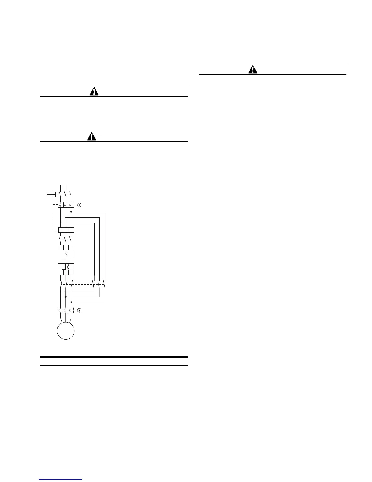
Bypass Operation
If you want to have the option of operating the motor with
the frequency inverter or directly from the input supply, the
input branches must be interlocked mechanically.
CAUTION
Debounced inputs may not be used in the safety circuit
diagram.
A changeover between the frequency inverter and the input
supply must take place in a voltage-free state.
WARNING
The frequency inverter outputs (U, V, W) must not be
connected to the input voltage (destruction of the
device, risk of fire).
Bypass Motor Control (Example)
CAUTION
Debounced inputs may not be used in the safety circuit
diagram.
Switch S1 must switch only when frequency inverter T1 is at
zero current.
Contactors and switches (S1) in the frequency inverter
output and for the direct start must be designed based on
utilization category AC-3 for the rated operational current of
the motor.
Connecting EX Motors
Note the following when connecting explosion-protected
motors:
●
The frequency inverter must be installed outside the EX
area
●
Note the branch- and country-specific standards for
explosion-protected areas (ATEX 100a)
●
Note the standards and information of the motor
manufacturer regarding operation on frequency inverters—
for example, if motor reactors (du/dt-limiting) or sinus
filters are specified
●
Temperature monitors in the motor windings (thermistor,
thermo-Click) are not to be connected directly to frequency
inverters but must be connected via an approved trigger
apparatus for EX areas
Sinusoidal Filter
Sinusoidal filters are connected in the output of the
frequency inverter. They allow the use of long motor cables
with reduced conducted and radiated emission.
The upstream sinusoidal filter enables the reduction of
losses and noise in the motor.
Disadvantage.
Sinusoidal filters have a system voltage drop
of around 30V per phase.
Note:
Sinusoidal filters must only be used with permanently
set pulse frequencies.
Item
Number Description
1
Input/bypass contactor
2
Output contactor
Q1
I
>
I
>
I
>
Q11
S1
M1
T1
M
3~
L1
L2
L3
L1 L2 L3
UVW
 Loading...


