Parameters
110 M-Max Series Adjustable Frequency Drive MN04020003E—October 2013 www.eaton.com
On the constant three-phase AC supply, the three-phase
asynchronous motor has a constant rotor speed (n
1
, P7.3,
rating plate specifications) according to the number of pole
pairs and input frequency. The slip here represents the
difference between the rotating field of the stator and that of
the rotor. In static operation, the slip is constant.
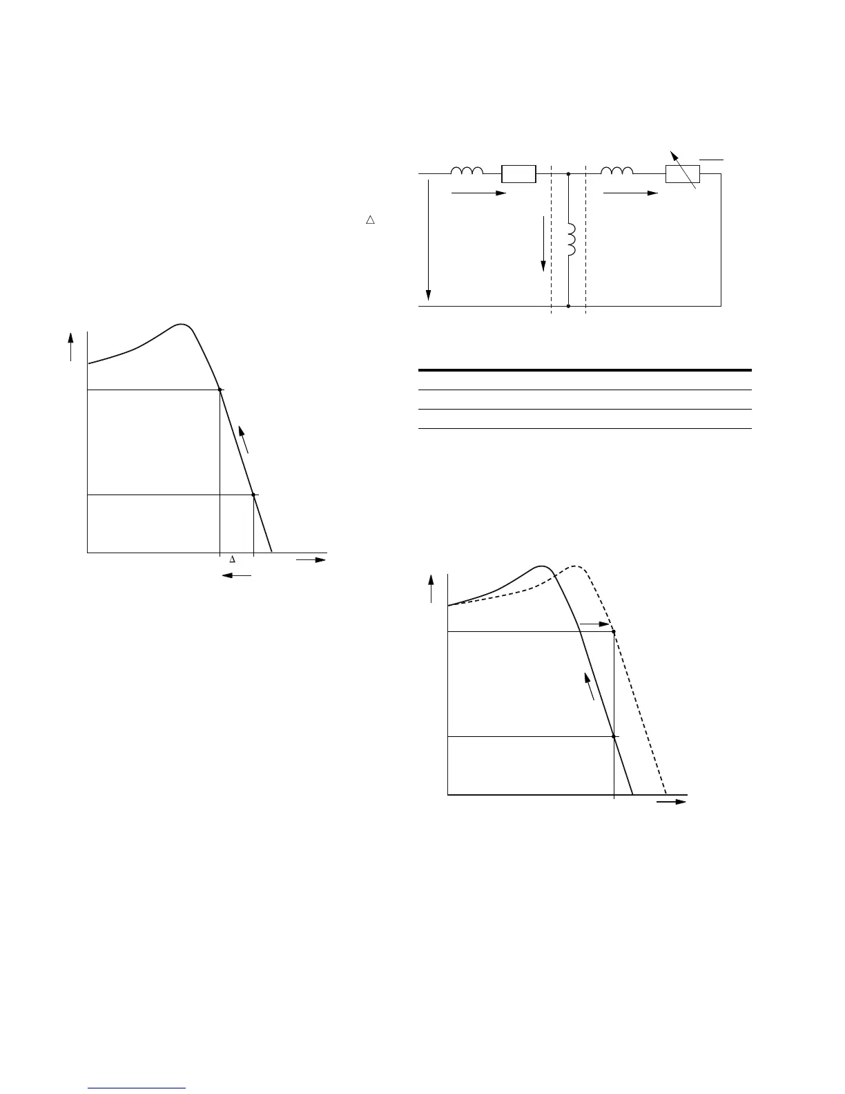
Load changes [1] at the motor shaft cause a larger slip ( n)
and thus a reduced rotor speed [2]. In controlled operation
(V/f-characteristic), the frequency inverter cannot
compensate this load-related speed difference. The speed
behavior of the motor is even, as in a constant AC supply.
Speed Behavior without Slip Compensation
In “Speed control” mode (P11.8 = 1), the frequency inverter
can compensate these load-related deviations. From the
measured voltage and current values of the stator winding
(u
1
, i
1
) the internal motor model calculates the required
manipulated variables for the flux variable i
μ
and the torque
variable i
w
. In the equivalent circuit diagram of the
three-phase motor, the load-related slip is shown as the
resistance R’
2
/s. In idle operation without a load, this
resistance approaches infinity, and approaches zero as the
load increases.
Equivalent Circuit Diagram for an Asynchronous Motor
An exact calculation requires the precise rating specifications
of the motor (parameter group 7). The speed control (P11.8 =
1) can then compensate the load-related slip deviations. The
simple illustration shows that, as the load torque increases
[1], the resulting speed reduction is compensated by an
increase in the output frequency
[2] (see figure below).
Speed Behavior with Slip Compensation
n
M
M
2
M
1
n
1
n
2
n
1
2
Item
Number Description
1 Stator winding
2 Air gap
3 Transformed rotor winding
R
1
X'
2
X
1
i
1
i
w
u
1
X
h
i
m
123
R'
2
s
M
M
2
M
1
n
1
n
1
2
 Loading...


