Installation
28 M-Max Series Adjustable Frequency Drive MN04020003E—October 2013 www.eaton.com
Fixing
You can mount an M-Max frequency inverter on screw
mounts or on a mounting rail.
Install the frequency inverter only on a nonflammable
mounting base (for example, on a metal plate).
Dimensions and weights of the M-Max frequency inverter
are located in the appendix.
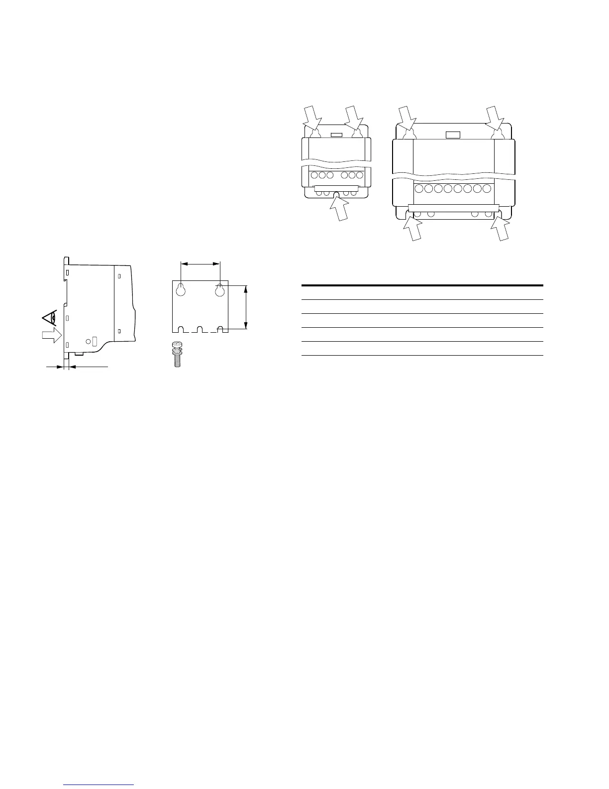
Fastening with Screws (FS1–FS5)
The number and arrangement of required bore holes
(mounting dimensions a1 and b1 shown in the figure below)
are also imprinted in the base plate of the M-Max device,
FS1–FS3.
Mounting Dimensions
Install the screws in the specified positions first. Then set
the frequency inverter on the prepared wall-mount and
tighten all screws.
Configuration for Mounting with Screws
0.28 in
(7 mm)
b1
a1
a1
mm [in]
b1
mm [in]
Mass
kg [lb]
Torque
Nm [ft-lb]
Mounting
Screw
FS1 38 [1.5] 147 [5.79] 0.55 [1.2] 1.3 [0.95] M4
FS2 62.5 [2.46] 182 [7.17] 0.7 [1.5] 1.3 [0.95] M4
FS3 75 [2.95] 242 [9.53] 0.99 [2.2] 1.3 [0.95] M5
FS4 140 [5.51] 351 [13.82] 8 [18.0] 4.6 [3.4] M6
FS5 140 [5.51] 398 [13.82] 10 [22.0] 4.6 [3.4] M6
FS1 and FS2 FS, FS4 and FS5
 Loading...


