Parameters
M-Max Series Adjustable Frequency Drive MN04020003E—October 2013 www.eaton.com 69
Analog Inputs, continued
Scaled Value Range (AI1, AI2)
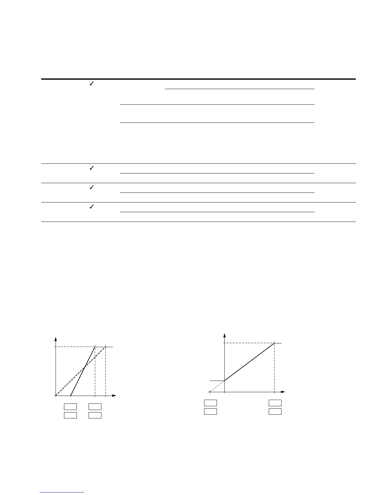
The following graphs show examples of the curve
characteristics of the scaled and non-scaled input signals.
Example A
P2.2 (P2.6) = 30%, P2.3 (P2.7) = 80%
The incoming analog input signal 0–10V (4–20 mA) is used
here in the selected range from 30 to 80%. This limited
signal range is predefined as 0–100% input signal (AI
scal
):
●
as frequency setpoint value from 0–f
max
(P6.4)
●
as a process variable from 0–100% actual value for the PID
controller
Example of Scaled Analog Input Signals
Example B
P2 (P2.6) = –30%, P2.3 (P2.7) = 100%
The incoming analog input signal 0–10V (4–20 mA) is not
evaluated in the selected range from 0–30%. In relation to
the 30%-signal, a constant offset signal of 23% is predefined
in this case. The scaled input signal (AI
scal
) is therefore
23–100%:
●
as frequency setpoint value: 23% f
max
–f
max
(P6.4)
●
as a process variable: 23–100% actual value for the PID
controller
Example of Scaled Analog Input Signals with Offset
PNU ID
Access
RUN Value/Range Description
Factory Setting
(P1.3)
P2.5 390 — AI2 signal range (analog input) 1
Depending on the switch position of microswitch S3
(FS = PID controller, actual value)
0 S3 = V: 0–10V, voltage signal
S3 = mA: 0–20 mA, current signal
1 With live-zero,
S3 = V: 2–10V, voltage signal
S3 = mA: 4–20 mA, current signal (FS, see P9.6)
At P8.1 it is possible to set the response of the MMX
to a setpoint error (live zero)
P2.6 391 — AI2 custom minimum 0.00
Like P2.2 —
P2.7 392 — AI2 custom maximum 100.00
Like P2.3 —
P2.8 389 — AI2, filter time 0.1
Like P2.4 —
0
0
30 100 (%)
100%
AL
scal.
80
P2.3
P2.7
P2.2
P2.6
0–30 100
100%
23%
P2.3
P2.7
P2.2
P2.6
(%)
AI
scal.
 Loading...


