Parameters
72 M-Max Series Adjustable Frequency Drive MN04020003E—October 2013 www.eaton.com
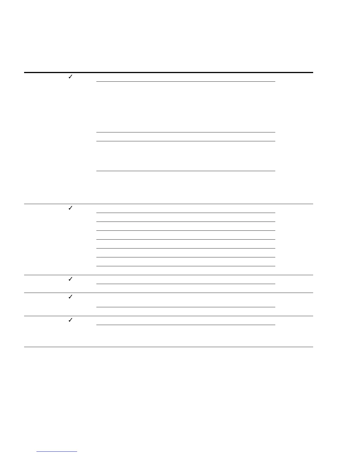
Digital Inputs
PNU ID
Access
RUN Value/Range Description
Factory Setting
(P1.3)
P3.1 300 — Start/Stop-Logic 3
0 P3.2 (FWD), P3.3 (REV), REAF
REAF (Restart after Fault) = Restart after an error message
Function same as P3.1 = 3
The automatic restart after an error message (FAULT) requires
setting P6.13 = 1
The rising edge of the control voltage at control signal terminal
8 (P3.2) or control signal terminal 9 (P3.3) is then not controlled
1 P3.2 (FWD) + P3.3 = REV (see Example A on Page 76)
2 P3.2 (Start pulse), P3.3 (Stop pulse)
Start and stop command via the control signal (P3.2 = Start)
(P3.3 = Stop) by a momentary pulse (+24V)
(see Example B on Page 76)
3 P3.2 (FWD), P3.3 (REV)
P3.2 (control signal terminal 8) starts the drive with a clockwise
rotating field (FWD) and P3.3 (control signal terminal 9) with an
anticlockwise rotating field (REV). Both control commands are
interlocked (exclusive OR)
P3.2 403 — Start signal/Start FWD (1) 1
0 Deactivated
1 Activated via control signal terminal 8 (DI1)
2 Activated via control signal terminal 9 (DI2)
3 Activated via control signal terminal 10 (DI3)
4 Activated via control signal terminal 14 (DI4)
5 Activated via control signal terminal 15 (DI5)
6 Activated via control signal terminal 16 (DI6)
P3.3 404 — STOP signal/Start REV(1) 2
Like P3.2 Allocation of the function to control signal terminals
P3.4 412 — Reverse (changes the direction of the field of rotation from
FWD to REV)
0
Like P3.2 Allocation of the function to control signal terminals
P3.5 405 — Ext. fault close (N/O) 0
Like 3.2 Allocation of the function to control signal terminals
Error message when applying +24V to the assigned control
signal terminal (DI1 to DI6)
 Loading...


