Installation
M-Max Series Adjustable Frequency Drive MN04020003E—October 2013 www.eaton.com 43
Digital Inputs with External Supply Voltage
(Negative Logic, Sink Type)
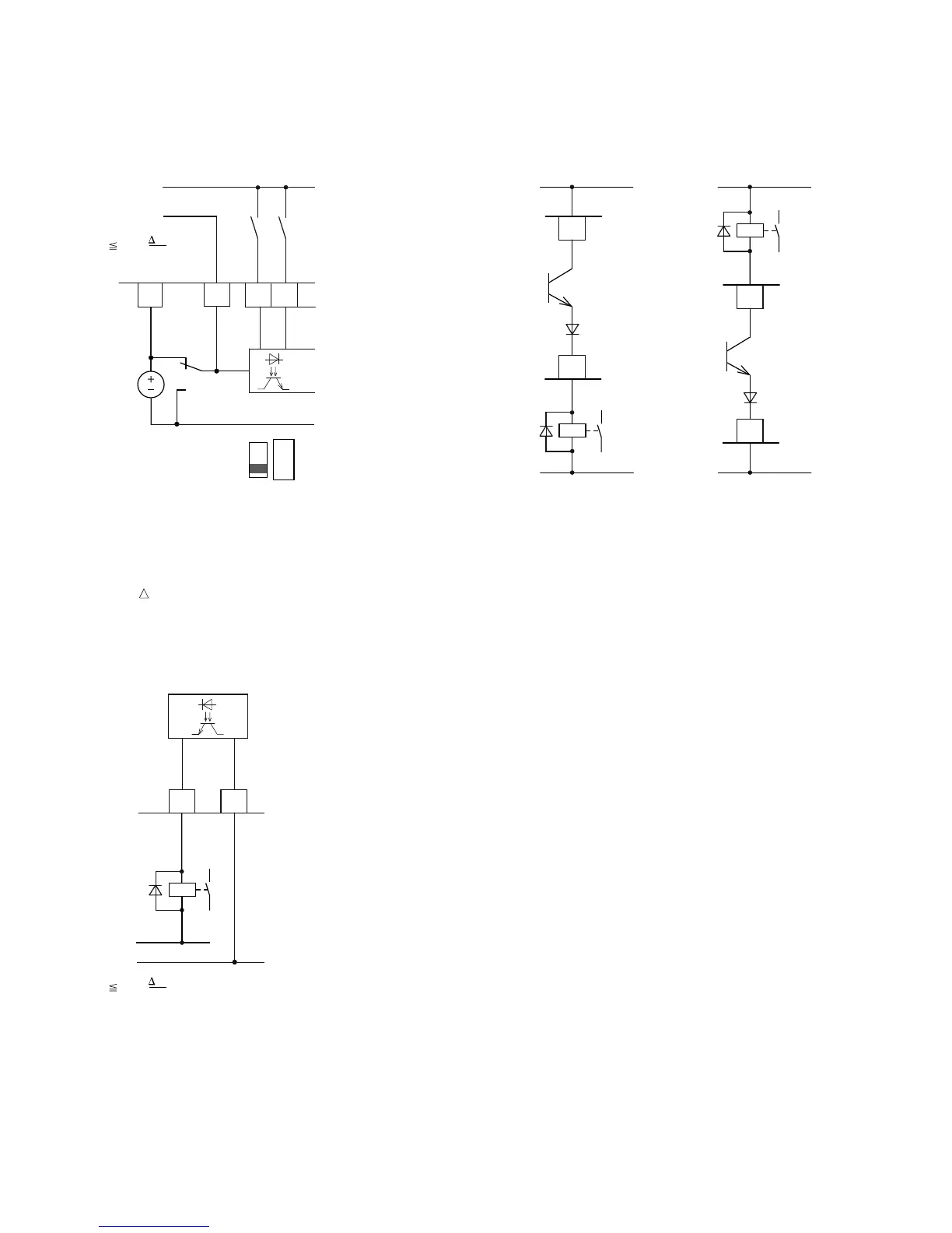
Digital Outputs (Transistor)
The transistor output (control signal terminal 13, DO–) can be
supplied with the internal control voltage (+24V) via control
signal terminal 20 (DO+) or with an external DC voltage of up
to +48V. The permissible residual ripple must be less than
±5% U
a
/U
a
. The maximum permissible load current is
50 mA.
Digital Output DO and Connection Examples
(Coupling Relay with Freewheeling Diode:
ETS4-VS3; Item No. 083094)
Connection Example and Operation of DO in
Source and Sink Type
The parameter assignment is described in “Digital Outputs
(P5)”on Page 78.
789
DI1
DI2
DI_COM
6
<50 mA
+24V Out
0V
+24V
S1
S1 = LOGIC–
(Sink Type)
LOGIC
– +
(
±5%
)
U
U
a
a
Ready
<50 mA
DO–
DO+
13 20
+
+24V
0V
(
±5%
)
U
U
a
a
+24V
0V
<50 mA
20
13
DO–
DO+
Source Type
+24V
0V
<50 mA
20
13
DO–
DO+
Sink Type
 Loading...


