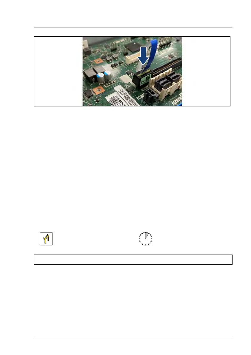
Figure 279: Installing the VROC module
▶
Connect the VROC module to the VROC connector on the system board.
Concluding steps
▶
Install the riser module 1, see "Installing a riser module" on page
69.
▶
"Reassembling" on page
57.
▶
"Connecting the power cord" on page 62.
▶
"Switching on the server" on page 66.
▶
If applicable, "Installing the front cover with lock" on page 66.
16.8.2 Removing the VROC module
Upgrade and Repair Unit
(URU)
Hardware: 5 minutes
Tools: tool-less
Preliminary steps
▶
If applicable, "Removing the front cover with lock" on page 48.
▶
"Shutting down the server" on page 48.
▶
"Disconnecting the power cord" on page 49.
System board and components
RX2530 M6 Upgrade and Maintenance Manual 383
 Loading...