Chapter 5: Troubleshooting
Diagnostic Readings
Service Manual 5-27
The date of last time the temperature and line voltage calibration was performed and current time settings
appear across the bottom of the screen.
5.9.2 DAC Voltage Test
The Digital/Analog Converter voltage is the over temperature voltage that is used by the system to verify
the computer independent circuitry is working. To manually test this circuit enter voltages using the arrows
from 0 to .5 V.
To perform the DAC Voltage test:
1. In service Mode, touch Diagnostic Readings in the left-navigation area.
The display area is populated.
2. Use the arrows to adjust the DAC Volt setting.
The DV value should match this value within 10mV.
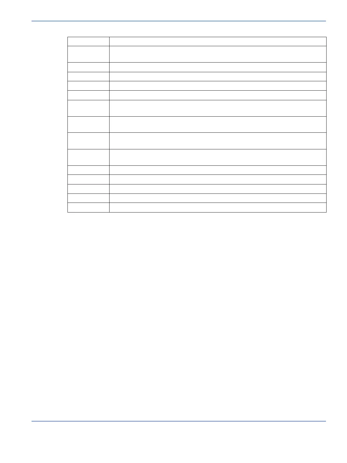
HFS High fan speed. Should be 1500 +/- 100 (measured at power up only).
HSP Heat sink sensor resistance. Should be 20000 ohms @ 25ºC. Refer to the Tips section
(5.3.3) for resistance versus temperature values.
LF 60Hz or 50Hz.
LFS Low fan speed. Should be 1000 +/- 100 (measured at power up only).
LV1 Line voltage in first mains circuit. Should be +/- 4V of LV2.
MC Motor current. Shows current drawn by the canopy or elevating base motor.
P11 Reading from the first thermistor in probe panel connector1. Should be +/- 0.5ºC of
P12 temperature.
P12 Reading from the second thermistor in probe panel connector 1. Should be +/- 0.5ºC
of P11 temperature.
P21 Reading from the first thermistor in probe panel connector 2. Should be +/- 0.5ºC of
P22 temperature.
P22 Reading from the second thermistor in probe panel connector 2. Should be +/- 0.5ºC
of P21 temperature.
RH Relative Humidity. % humidity read in the patient chamber.
SC Scale counts corrected. (1 count = 1 gram)
SR Scale counts raw.
TV Thermistor voltage. Voltage of thermistor circuits located on the mother board.
VR Voltage reference. Independent voltage reference. Should be 1.235V + 1%.

 Loading...


