Chapter 7: Repair Procedures
Left Rail Internal Repairs
Service Manual 7-27
23. Reinstall the connection panel at the bottom of the electrical enclosure. Fasten the control panel cover
to the back of the enclosure.
7.5 Left Rail Internal Repairs
7.5.1 Removing the Inner Rail Assembly
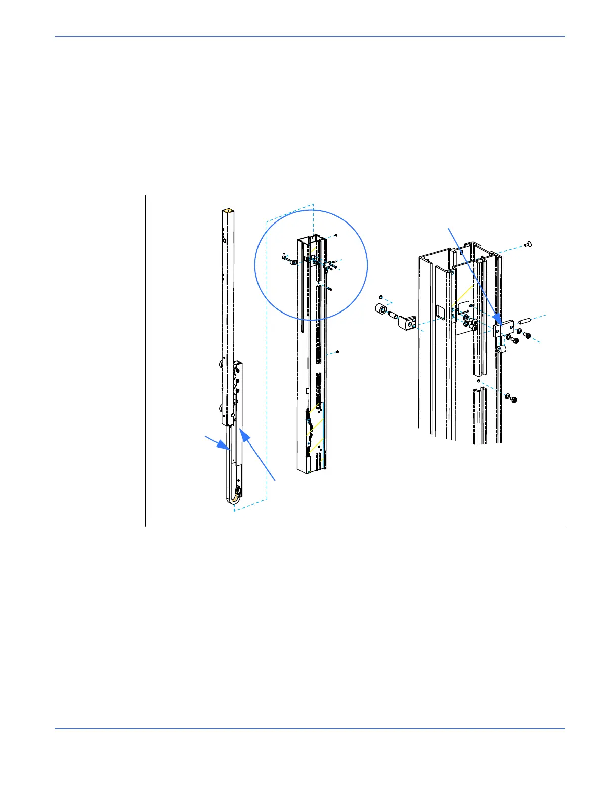
Refer to “Figure 7-28 Left Inner Rail”.
1. Using a 2.5 mm hex key, remove the 2 screws in the rear dovetail of the upright that secure the cable
carrier channel to the inside of the upright. One screw is located at the top of the upright; the other is
half way down. Using a 3 mm hex key, remove the side roller bracket. Pull the entire rail assembly out of
the upright.
2. Remove the pinch guard by sliding it up then pulling it off.
FIGURE 7-28. Left Inner Rail
Side roller bracket
Cable carrier
Cable carrier channel
Lift rail
Left upright

 Loading...


