Chapter 7: Repair Procedures
Right Rail Assembly Repair Procedures
7-18 Service Manual
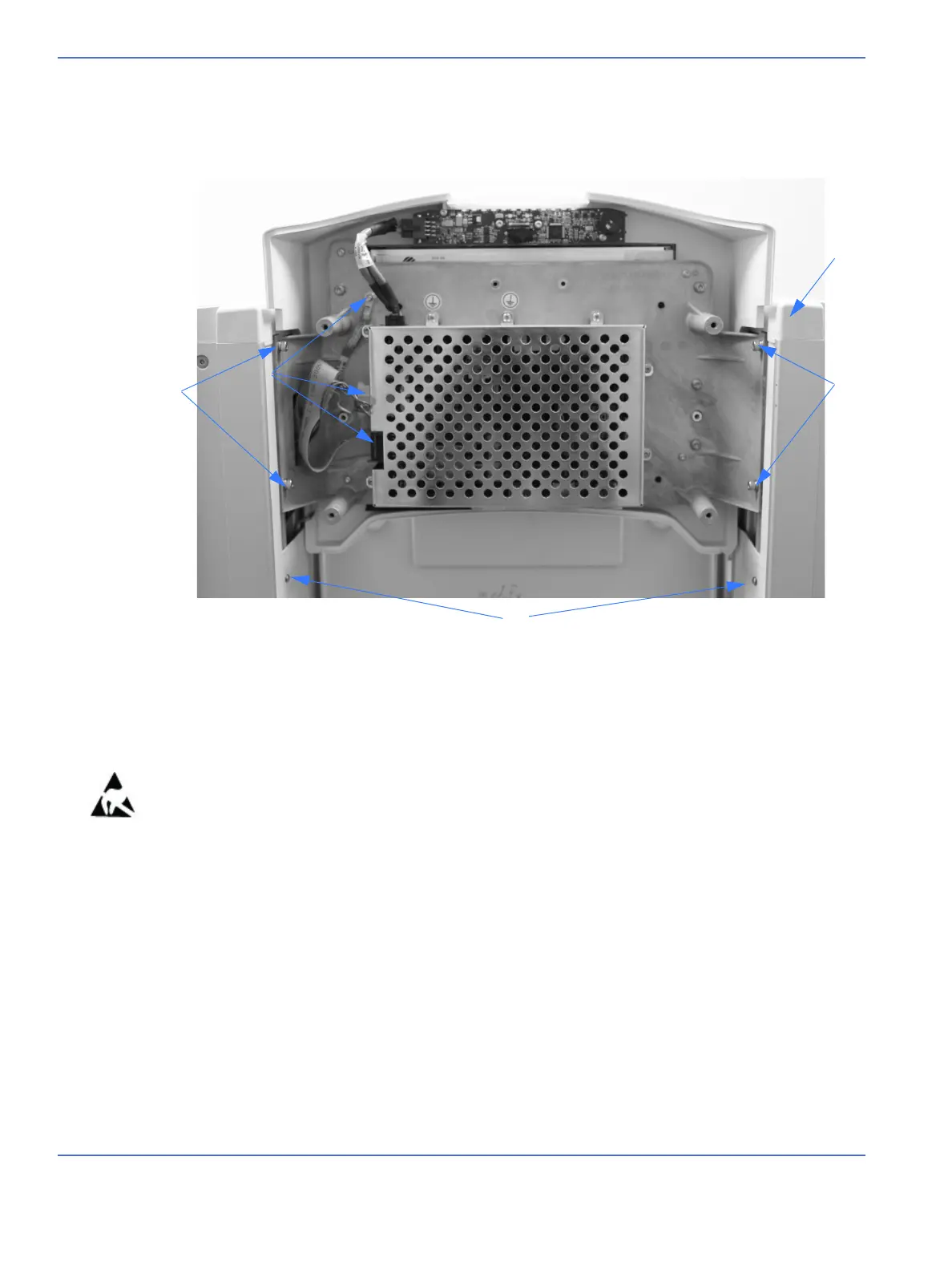
4. Using a 3 mm hex key, loosen the 4 screws that secure the display module to the nut bars on either side
of the display module 2-3 turns. (item 2) Do not remove the screws. Using a 2 mm hex key remove the
two lower screws holding the nut bar (item 3). While guiding the power and data harnesses through the
access hole, carefully pull the display module along with the x2 nut bars up and out of the rails.
7.4 Right Rail Assembly Repair Procedures
Note: The entire rail assembly is available or the individual parts may be replaced. Refer to “Illustrated
Parts” on page 8-1 for part numbers.
7.4.1 Removing the Right Upright (Motor Side)
Refer to “Figure 7-1 Heater Housing Cover and Soffit”, “Figure 7-22 Disconnecting Heater Door Cable”,
“Figure 7-23 Rail Decorative Strips, End Caps, and Wire Cover”, “Figure 7-24 Removing the Lift Motor”,
“Display Head Removal” on page 7-17, and “Figure 7-30 Re-attaching the Upright”.
FIGURE 7-21. Display Head Assembly
2
1
3
1
3

 Loading...


