Chapter 7: Repair Procedures
Display Module Repairs
7-68 Service Manual
7.19.4 LCD Display Assembly
7.19.4.1 LCD Display Disassembly
1. Power on the unit.
2. Using the foot or hand switch, raise the Canopy all the way to the top.
3. Remove the display housing rear cover. See “Rear Cover” on page 7-65.
4. Disconnect the alarm board connector from the SBC board.
5. Working from the back of the device, using a T20 torx tool, remove the six (40 x 12) thread forming
screws, three on the left and three on the right that mount the front bezel to the carrier plate and
carefully remove the bezel.
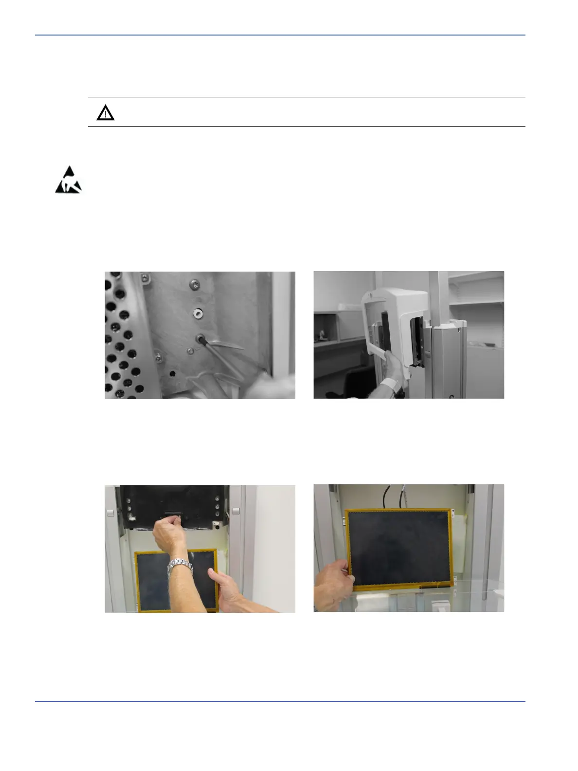
Note: When completing the following steps, it is possible to hold the display using one hand (Figure 7-65,
left image). However, it will be helpful to place the clear plastic mattress support as a Temporary
Support (Figure 7-65, right image) over the north and side walls to provide a resting place for the
display while working with the harnessing.
Caution: Failure to raise the Canopy before loosening the bezel mounting screws may result
in damage to the Display Assembly.
FIGURE 7-64. Remove the Bezel
FIGURE 7-65. Temporary Support

 Loading...


