Chapter 7: Repair Procedures
Control Board
Service Manual 7-57
7.13.1.1 Power Fail Battery
The PF Battery snaps into a holder on the side of the probe panel housing. It has two snap connectors at its
top. When replacing the battery, its easier to first connect the terminals then push the battery into its holder.
Note: Run the device for at least two hours to charge the new battery before using the device. The PF
Battery charges only when the device is powered on.
7.13.2 Control Panel Components
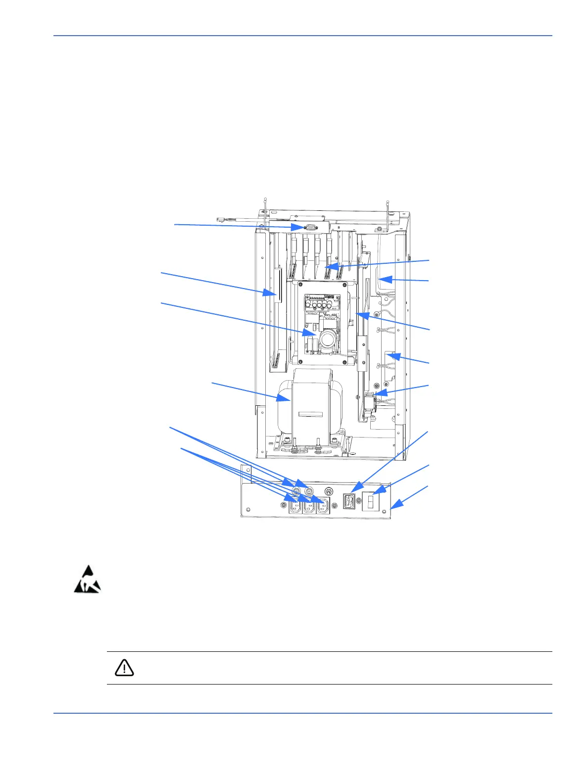
Refer to “Figure 7-53 Electronics Enclosure”.
Using a 2.5 mm hex key, loosen the 2 screws in the keyhole slots and remove the 6 remaining screws that
secure the control panel cover, then remove the cover. Now you can access the electrical components in
“Electronics Enclosure” on page 7-57.
7.14 Control Board
FIGURE 7-53. Electronics Enclosure
RS-232 connector
Control board
Power supply
Heater Isolation transformer
Circuit breakers
Power outlets
Card cage
Toroidal transformer
Relay board
Incubator solid state relay
Warmer solid state relay
Line filter
Power switch
Connection panel
Caution: To avoid damaging a harness, make sure you do not pull the harness by the cable
wires. Instead, use the connector body to disengage or to engage the connectors.

 Loading...


