Chapter 7: Repair Procedures
Control Panel and Display Module Procedures
7-56 Service Manual
7.13 Control Panel and Display Module Procedures
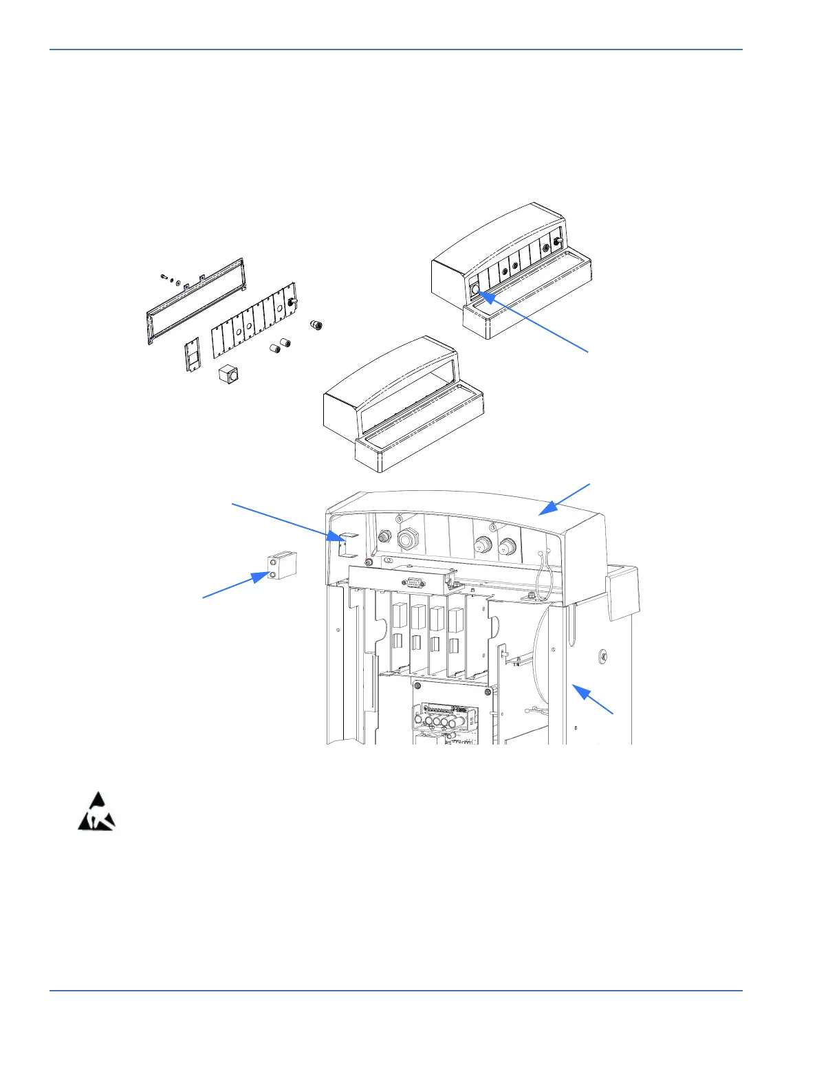
7.13.1 Probe Panel
Refer to “Figure 7-52 Probe Panel” and “Figure 8-1 Probe Panel Assembly”.
1. Using a 2.5 mm hex key, loosen the 2 screws in the keyhole slots and remove the 6 remaining screws
that secure the control panel cover, then remove the cover. Disconnect the wire harnesses coming from
the probe panel.
2. Remove the 2 screws at the bottom corners that hold the probe panel to the enclosure.
3. Remove the probe panel assembly.
4. While tilting the panel enclosure forward, use a 3 mm hex key to remove the 4 screws that hold the
panel frame in place. Add new connectors through the panel frame as appropriate.
Note: The power switch panel must be on the far left. The position of the remaining panels is not critical.
FIGURE 7-52. Probe Panel
Power switch
Probe panel housing
Electrical enclosure
Probe panel housing
PF Battery holder
PF Battery

 Loading...


