Chapter 7: Repair Procedures
Right Rail Assembly Repair Procedures
7-24 Service Manual
7.4.3.2 Replacing Rollers and Tension Springs
Refer to “Figure 7-26 Rollers and Tensioning Spring”.
1. The rollers can be removed one at a time by removing the screw (4 mm hex key) at their hub and pulling
off the roller and bearing. When reinstalling, torque the screws to 45 in. lbs (reference).
2. To replace the roller tensioning spring, first use needle nose pliers to pull the tension spring off the roll
pin at the end of the lift rail. Then take off the 2 center rollers and slide the tensioning plate out of the lift
rail. Remove the old spring.
3. Reinstall the 2 center rollers. Use a hex key in the center access slot to lift the tensioning plate up so
that you can screw the rollers into the holes in the plate. Torque rollers screws to 45 inch lbs (reference).
4. Using pliers, pull the tensioning spring up onto the roll pin at the end of the rail.
7.4.3.3 Separating the Lift Rail from the Belt Channel
Refer to “Figure 7-25 Right Rail Disassembly”.
1. If you can access the screw head through the access hole in the lift rail go to step 2. If you can not
access the screw, push the lift rail and the belt channel together and lift the belt block up past the roll
pin so you can see the screw head through the access hole in the lift rail.
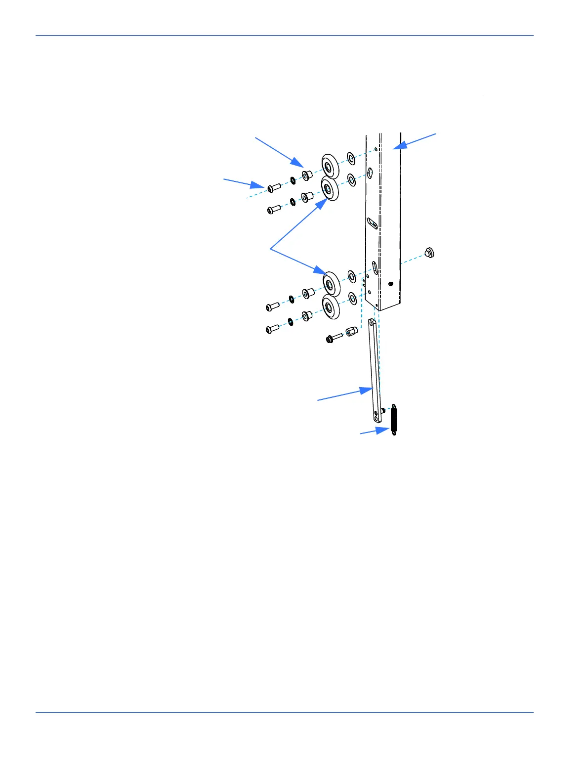
FIGURE 7-26. Rollers and Tensioning Spring
Bearing
Roller mounting screw
Center rollers
Tensioning plate
Roller tensioning spring
Lift rail

 Loading...


