Chapter 7: Repair Procedures
Display Module Repairs
Service Manual 7-69
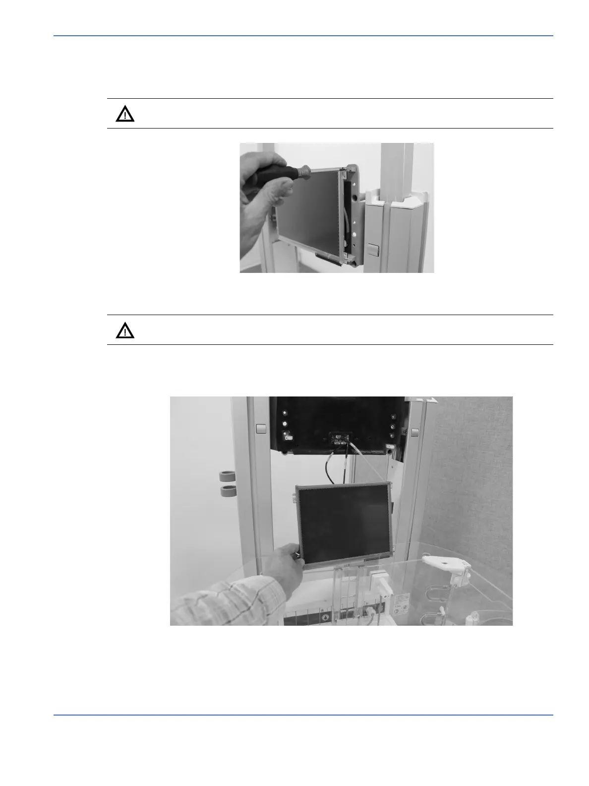
6. Working from the front of the device, using a T10 torx tool, remove the two (30 x 10) thread forming
screws that mount the right hand side of the LCD display assembly to the display stand offs.
.
7. Slide the display to the right to remove it from the left hand standoffs. Gently set the display on top of
the temporary support (OmniBed) or Incubator hood to reduce the stress on the harnesses while
accessing the harness connections to the SBC PCA.
Caution: Be sure to support the display during disassembly to avoid damaging the display.
Caution: The leads on the Display Harnesses are fragile. Care when removing the Display
Assembly is warranted.
FIGURE 7-66. Remove Thread Forming Screws
FIGURE 7-67. Set Down Display

 Loading...


