Chapter 8: Illustrated Parts
Servo Control Oxygen
Service Manual 8-51
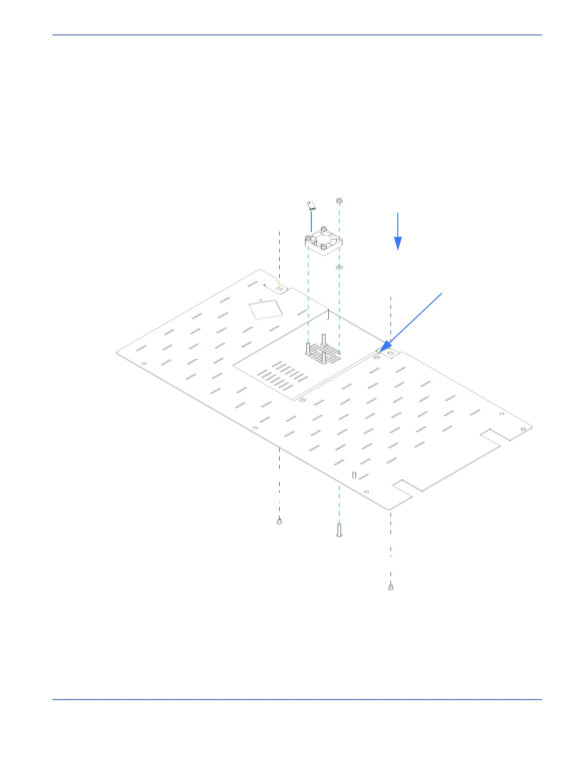
1. Nylok nut, M4...................................................................... 6600-0714-402
2. Cooling fan assembly*................................................... 6600-1523-700
3. Flat washer, M4.................................................................. 6600-0712-403
4. Screw, M4x20L Button Hd............................................. 6600-0706-412
5. Screw, captive 8 mm long.............................................6600-0868-401
6. Screw, SEMS M4 x 6 Button Hd...................................6600-0908-402
Parts Not Shown
Cable tie ................................................................................ 6600-0384-400
*Install the fan so that the flow arrow on the side points down, away from chassis.
FIGURE 8-27. Servo Control Oxygen Cooling Fan
5
3
1
2
4
6
AIR FLOW

 Loading...


