4.9 Stack Status after Completion of Exception Handling
The status of the stack after an exception-handling sequence is described below.
Table 4-3 shows the stack after completion of the exception-handling sequence for various types
of exceptions in the minimum and maximum modes.
Table 4-3 Stack after Exception Handling Sequence
Note: The RTE instruction returns to the next instruction after the instruction being executed when
the exception occurred.
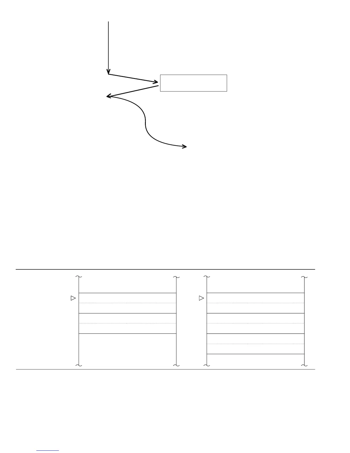
← DTC interrupt request
MOV.W R0,@H'FF00
Program flow
To NMI exception-handling sequence
← NMI interrupt request
After data transfer cycle, CPU
executes next instruction before
branching to exception handling
ADD.W R2,R0
MOV.W #H'FF02,R0
Data transfer cycle
(Example)
.
.
.
.
.
.
.
.
Exception Factor Minimum Mode Maximum Mode
Trace
Interrupt
Trap
Zero divide
(DIVXU)
SP SR (upper byte) TP:SP SR (upper byte)
SR (lower byte) SR (lower byte)
Next instruction address (upper byte) Don’t-care
Next instruction address (lower byte) Next instruction page (8 bits)
Next instruction address (upper byte)
Next instruction address (lower byte)
94
Downloaded from Elcodis.com electronic components distributor

 Loading...
