Table 20-6 Timing Conditions of On-Chip Supporting Modules
Conditions: VCC = 5.0V ±10%, AVCC = 5.0V ±10%, ø = 0.5 to 10MHz, VSS = 0V
Ta = –20 to +75˚C (Regular Specifications)
Ta = –40 to +85˚C (Wide-Range Specifications)
6MHz 8MHz 10MHz Measurement
Item Symbol Min Max Min Max Min Max Unit Conditions
FRT Timer output delay time tFTOD – 100 – 100 – 100 ns See figure 20-14
Timer input setup time tFTIS 50 – 50 – 50 – ns
Timer clock input setup time tFTCS 50 – 50 – 50 – ns See figure 20-15
Timer clock pulse width tFTCWL,
tFTCWH 1.5 – 1.5 – 1.5 – tcyc
TMR Timer output delay time tTMOD – 100 – 100 – 100 ns See figure 20-16
Timer clock input setup time tTMCS 50 – 50 – 50 – ns See figure 20-17
Timer clock pulse width tTMCWL,
tTMCWH 1.5 – 1.5 – 1.5 – tcyc
Timer reset input setup time tTMRS 50 – 50 – 50 – ns See figure 20-18
PWM Timer output delay time tPWOD – 100 – 100 – 100 ns See figure 20-19
SCI Input clock cycle (Async) tScyc 2– 2– 2–tcyc See figure 20-20
(Sync) 4 – 4 – 4 – tcyc
Input clock pulse width tSCKW 0.4 0.6 0.4 0.6 0.4 0.6 tScyc
Transmit data delay time (Sync) tTXD – 100 – 100 – 100 ns See figure 20-21
Receive data setup time (Sync) tRXS 100 – 100 – 100 – ns
Receive data hold time (Sync) tRXH 100 – 100 – 100 – ns
Port Output data delay time tPWD – 100 – 100 – 100 ns See figure 20-13
Input data setup time tPRS 50 – 50 – 50 – ns
Input data hold time tPRH 50 – 50 – 50 – ns
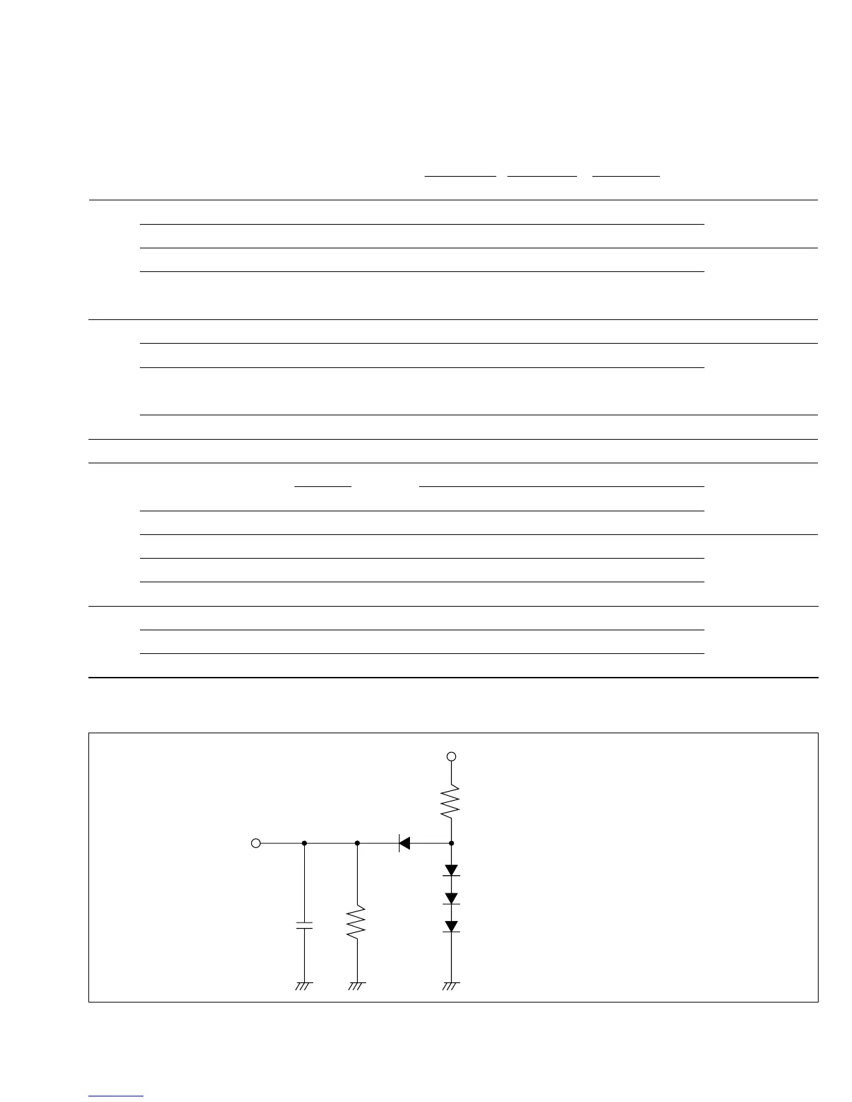
• Measurement Conditions for AC Characteristics
H8/532
output pin
5 V
C
R
H
C
R
R
Input/output timing reference levels
Low:
High:
= 90 pF: P1, P2, P3, P4, P5, P6
= 30 pF: P7, P9
= 2.4 k
= 12 k
0.8V
2.0V
L
H
RL
C = 90 pF: P1, P2, P3, P4, P5, P6
= 30 pF: P7, P9
R
L = 2.4 kΩ
R
H = 12 kΩ
Input/output timing reference levels
Low: 0.8V
High: 2.0V
Figure 20-3 Output Load Circuit
325
Downloaded from Elcodis.com electronic components distributor

 Loading...
