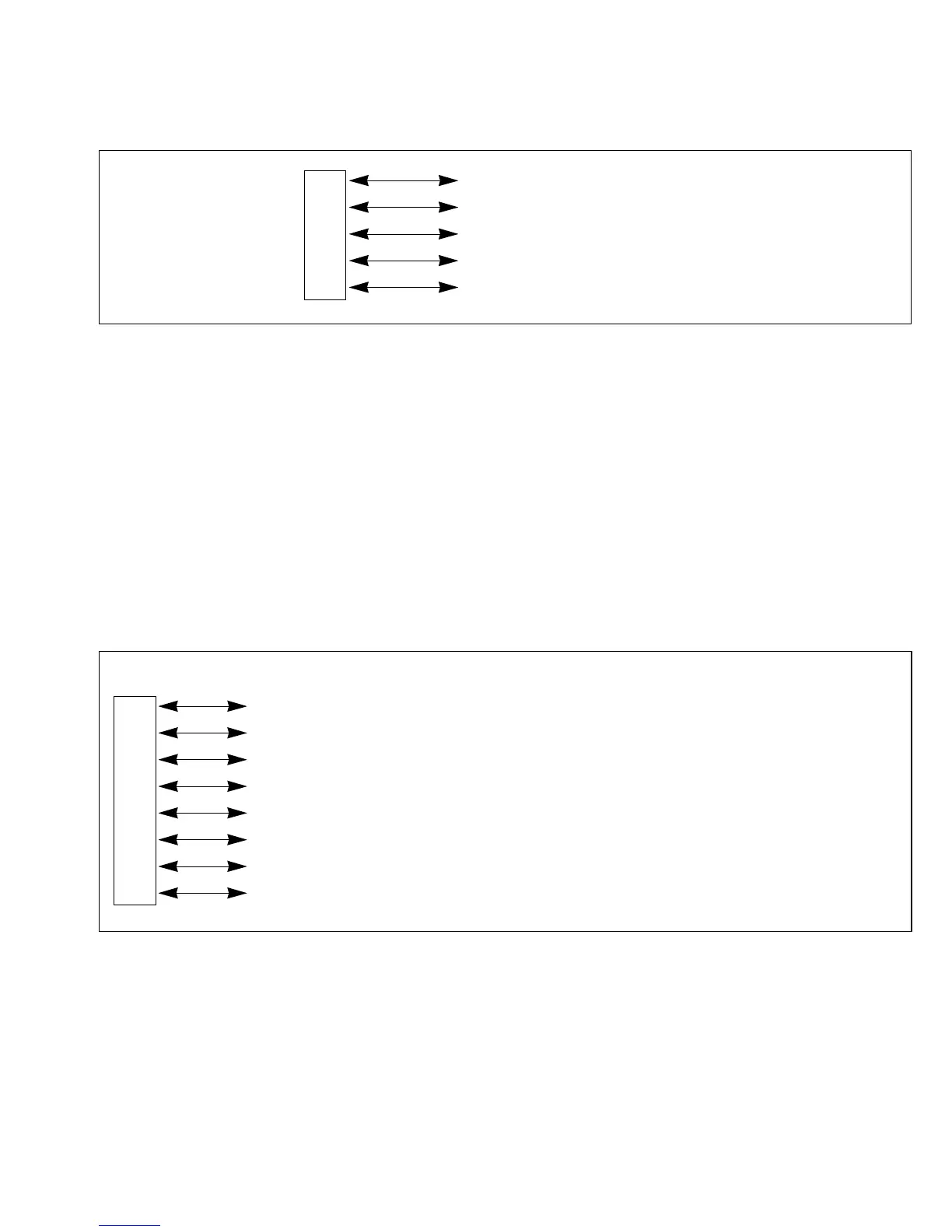
Pin Functions in Single-Chip Mode: In the single-chip mode (mode 7), each of the port 2
pins can be designated as an input pin or an output pin, as indicated in figure 9-4, by setting the
corresponding bit in P2DDR to “1” for output or clearing it to “0” for input.
9.4 Port 3
9.4.1 Overview
Port 3 is an 8-bit input/output port with the pin configuration shown in figure 9-5. In the
expanded modes it operates as the external data bus (D7 – D0). In the single-chip mode it operates
as a general-purpose input/output port.
Outputs from port 3 can drive one TTL load and a 90pF capacitive load. They can also drive a
Darlington transistor pair.
P24 (input/output)
Port P2
3 (input/output)
2P2
2 (input/output)
P2
1 (input/output)
P2
0 (input/output)
Pin Expanded Modes Single-Chip Mode
P3
7 / D7 D7 (input/output) P37 (input/output)
P3
6 / D6 D6 (input/output) P36 (input/output)
P3
5 / D5 D5 (input/output) P35 (input/output)
Port P3
4 / D4 D4 (input/output) P34 (input/output)
3P3
3 / D3 D3 (input/output) P33 (input/output)
P3
2 / D2 D2 (input/output) P32 (input/output)
P3
1 / D1 D1 (input/output) P31 (input/output)
P3
0 / D0 D0 (input/output) P30 (input/output)
Figure 9-4 Port 2 Pin Functions in Single-Chip Mode
Figure 9-5 Pin Functions of Port 3
151
Downloaded from Elcodis.com electronic components distributor

 Loading...
